
Micro-incision IOL and positioning of the IOL in the eye
a micro-incision and positioning technology, applied in the field of intraocular lenses, can solve the problems of impairing the vision of patients, human eye diseases, etc., and achieve the effects of reducing post-surgical recovery time, reducing the size of the incision, and reducing the complexity of the surgical procedur
Patent Information
- Authority / Receiving Office
- US · United States
- Patent Type
- Patents(United States)
- Current Assignee / Owner
- Publication Date
- 2017-02-21
Smart Images
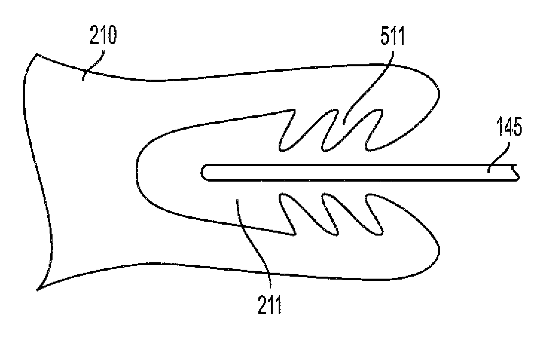
Figure 1 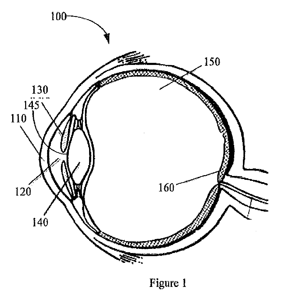
Figure 2 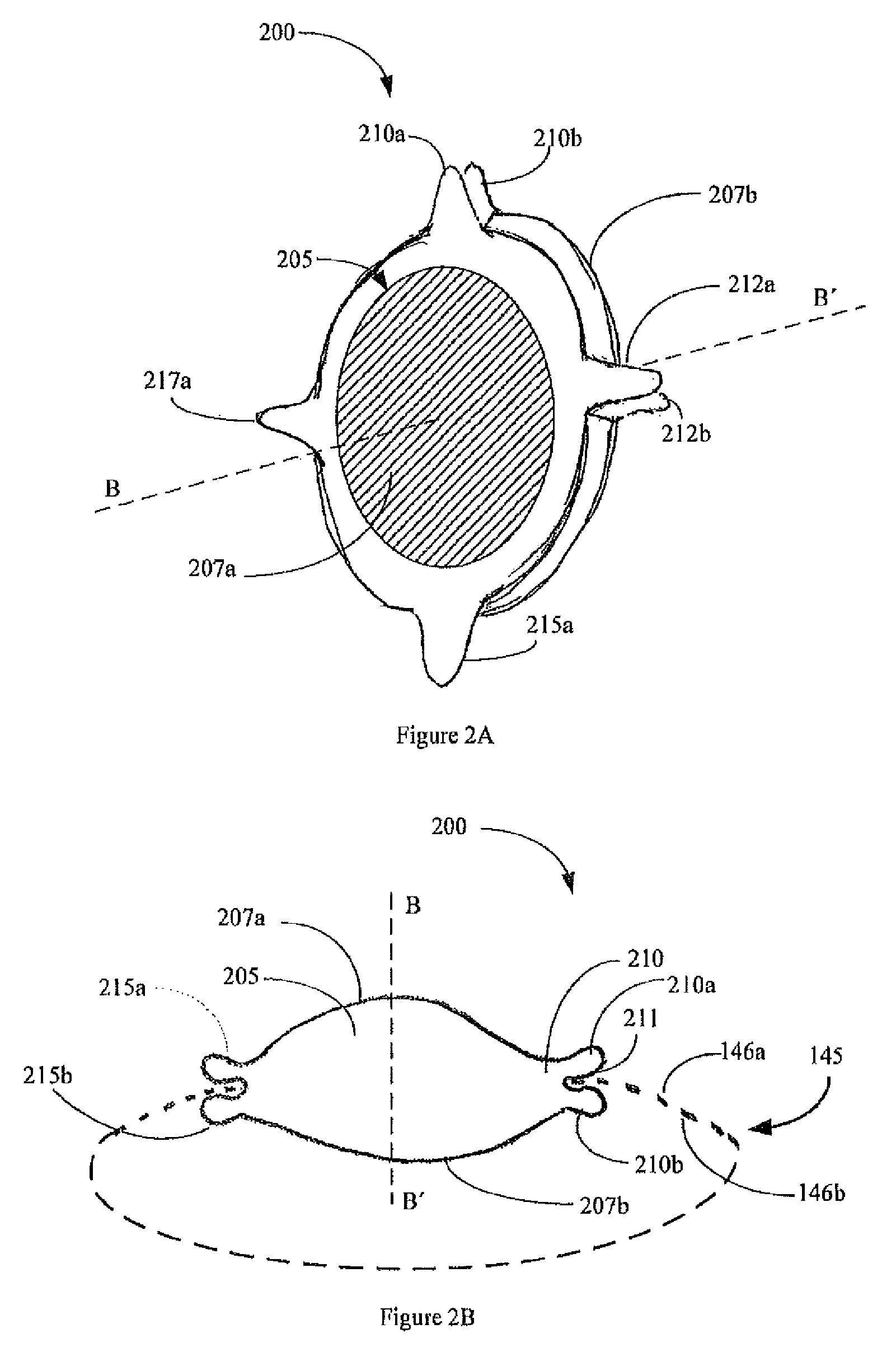
Figure 3
Abstract
Description
CROSS-REFERENCES TO RELATED APPLICATIONS
[0001] This application claims priority to U.S. Provisional Application No. 61 / 779,505 filed on Mar. 13, 2013, the entire contents of which are incorporated herein by reference.BACKGROUND
[0002] Field of the Invention
[0003] This invention relates generally to intraocular lenses, and more specifically, to compact intraocular lenses that can be implanted in the eye with a micro-incision.
[0004] Description of the Related Art
[0005] A human eye can suffer diseases that impair a patient's vision. For example, a cataract can increase the opacity of the lens, ultimately leading to blindness. To restore the patient's vision, the diseased lens may be surgically removed and replaced with an artificial lens, known as an intraocular lens, or IOL. As another example, to treat eye conditions such as myopia, hypermetropia or presbyopia, an intraocular lens can be surgically implanted in the eye to replace or supplement the natural eye.
[0006] IOLs can be inserted in ...
Examples
Embodiment Construction
[0019]It is to be understood that the figures and descriptions of the present invention have been simplified to illustrate elements that are relevant for a clear understanding of the present invention, while eliminating, for the purpose of clarity, many other elements found in typical lenses, lens systems and lens design methods. Those of ordinary skill in the arts may recognize that other elements and / or steps are desirable and may be used in implementing the embodiments described herein.
[0020]FIG. 1 is a schematic drawing of a human eye 100. Light enters the eye from the left of FIG. 1, and passes through the cornea 110, the anterior chamber 120, a pupil defined by the iris 130, and enters the lens 140. After passing through the lens 140, light passes through the vitreous chamber 150, and strikes the retina 160, which detects the light and converts it to a signal transmitted through the optic nerve to the brain (not shown).
[0021]The natural lens 140 is a transparent crystalline bi...