
Digital architecture for delta-sigma RMS-to-DC converter
Patent Information
- Authority / Receiving Office
- US · United States
- Current Assignee / Owner
- Publication Date
- 2017-02-21
- Estimated Expiration
- Not applicable · inactive patent
Smart Images
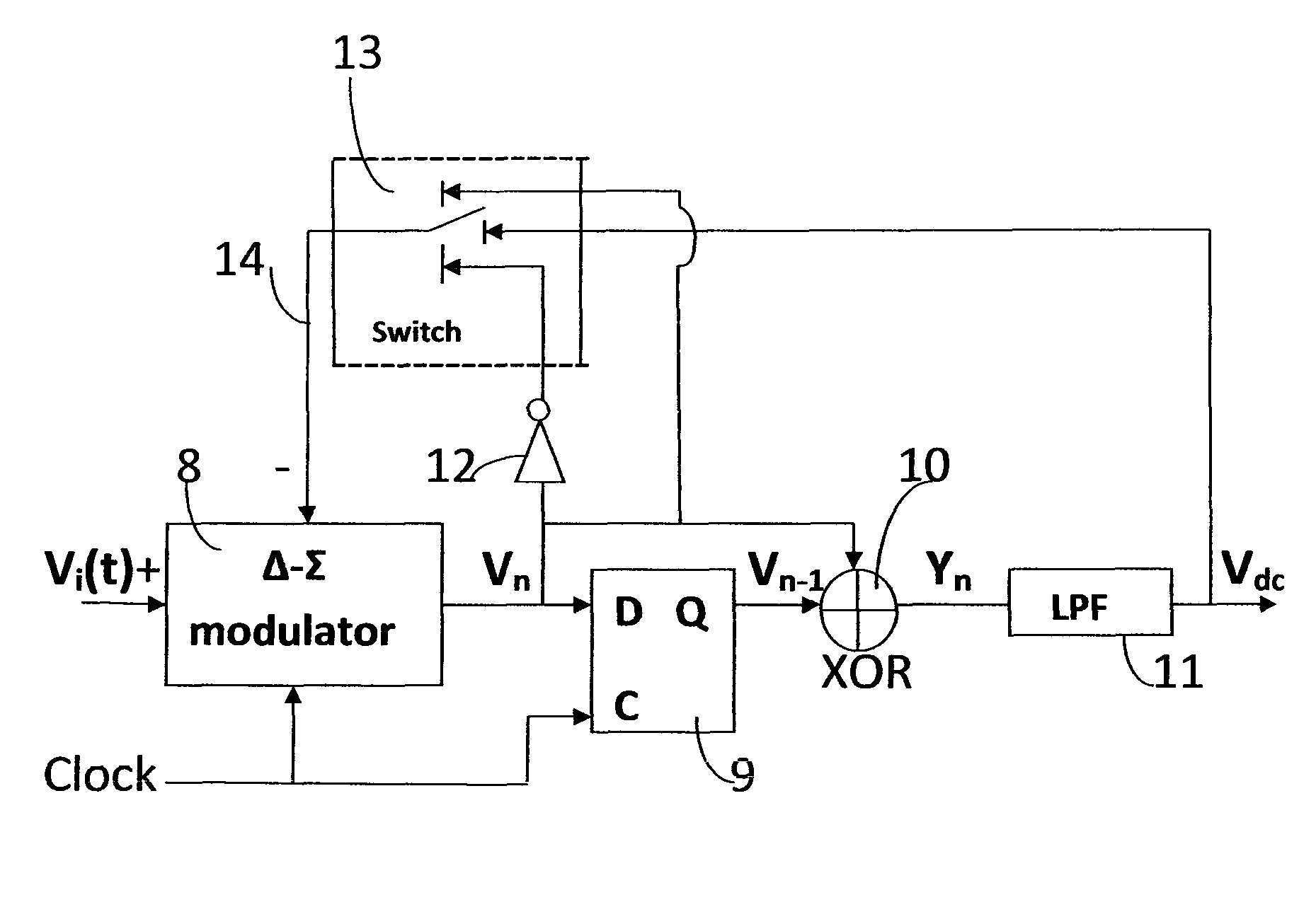
Figure 1 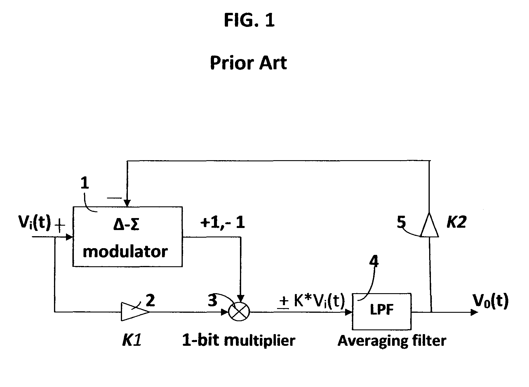
Figure 2 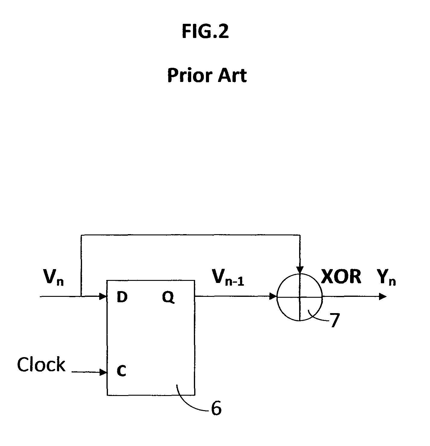
Figure 3
Abstract
Description
STATEMENT REGARDING FEDERALLY SPONSORED R&D
[0001] These research results are not sponsored by Government grants.CROSS REFERENCES TO RELATED APPLICATIONS
[0002] Dj. Zrilic, U.S. Pat. No. 5,349,353, Date of patent: Sep. 20, 1994
[0003] Dj. Zrilic, U.S. Pat. No. 6,285,306 B1, Date of Patent: Sep. 4, 2001
[0004] J. G. Petrofsky, U.S. Pat. No. 6,587,061 B2, Date of Patent: Jul. 1, 2003
[0005] Dj. Zrilc, U.S. Pat. No. 9,141,339 B2, Date of Patent: Sep. 22, 2015
[0006] Dj. Zrilic, U.S. patent application Ser. No. (Pending): 29 / 505,520, Dec. 3, 2015.NAME OF PARTIES TO A JOINT RESEARCH AGREEMENT
[0007] Individual project of Dr. Djuro G. ZrilicBACKGROUND OF INVENTION
[0008] 1. Field of the Invention
[0009] (0001) The present invention relates to methods and apparatus for the nonlinear processing of delta-modulated pulse stream. The analog input signal is first converted into a one-bit high density pulse stream using the delta-sigma modulator (Δ-ΣM) as an analog-to-digital converter (ADC). Δ-ΣM is highly overs...
Examples
Embodiment Construction
Definition
[0031]RMS or Root Mean Square is a fundamental measurement of the magnitude of an alternate current (AC) signal. Its definition can be both mathematical and practical. Mathematically the RMS is defined as:
Vrms=square root of [average(V2)]
[0032]This formula involves squaring the signal, taking the average, and obtaining the square root. The averaging time must be sufficiently long to allow filtering at the lowest frequencies of the operation desired.
[0033]Practical definition: the RMS value assigned to an AC is the amount of direct current (DC) required to produce an equivalent amount of heat in the same load.
How to Make the Invention
[0034]A full embodiment of the circuit for the RMS-to-DC operation on Δ-ΣM signal is shown in FIG. 3. Its operation is as follows:
[0035]The input signal Vi(t) is converted by means of Δ-εM (8) into a digital pulse stream Vn. Squaring of a pulse stream Vn is achieved by a simple logic circuit which consists of D flip-flop and X-OR gate. This cir...