
Wireless communication system
a communication system and wireless technology, applied in the field of wireless communication systems, can solve the problems of affecting the quality of communication, so as to compensate for the degradation of communication quality
Patent Information
- Authority / Receiving Office
- US · United States
- Patent Type
- Patents(United States)
- Current Assignee / Owner
- Publication Date
- 2017-09-12
Smart Images
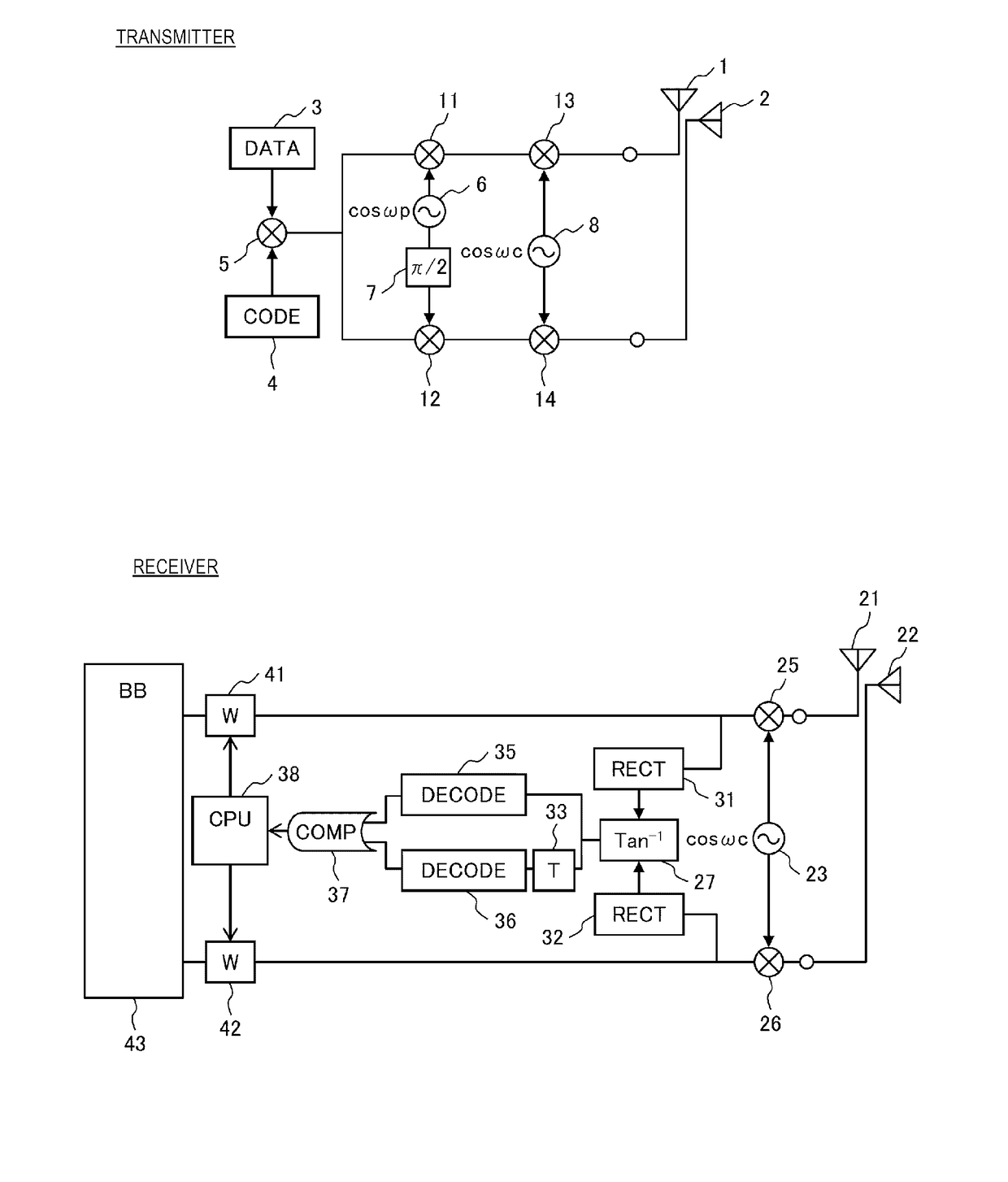
Figure 1 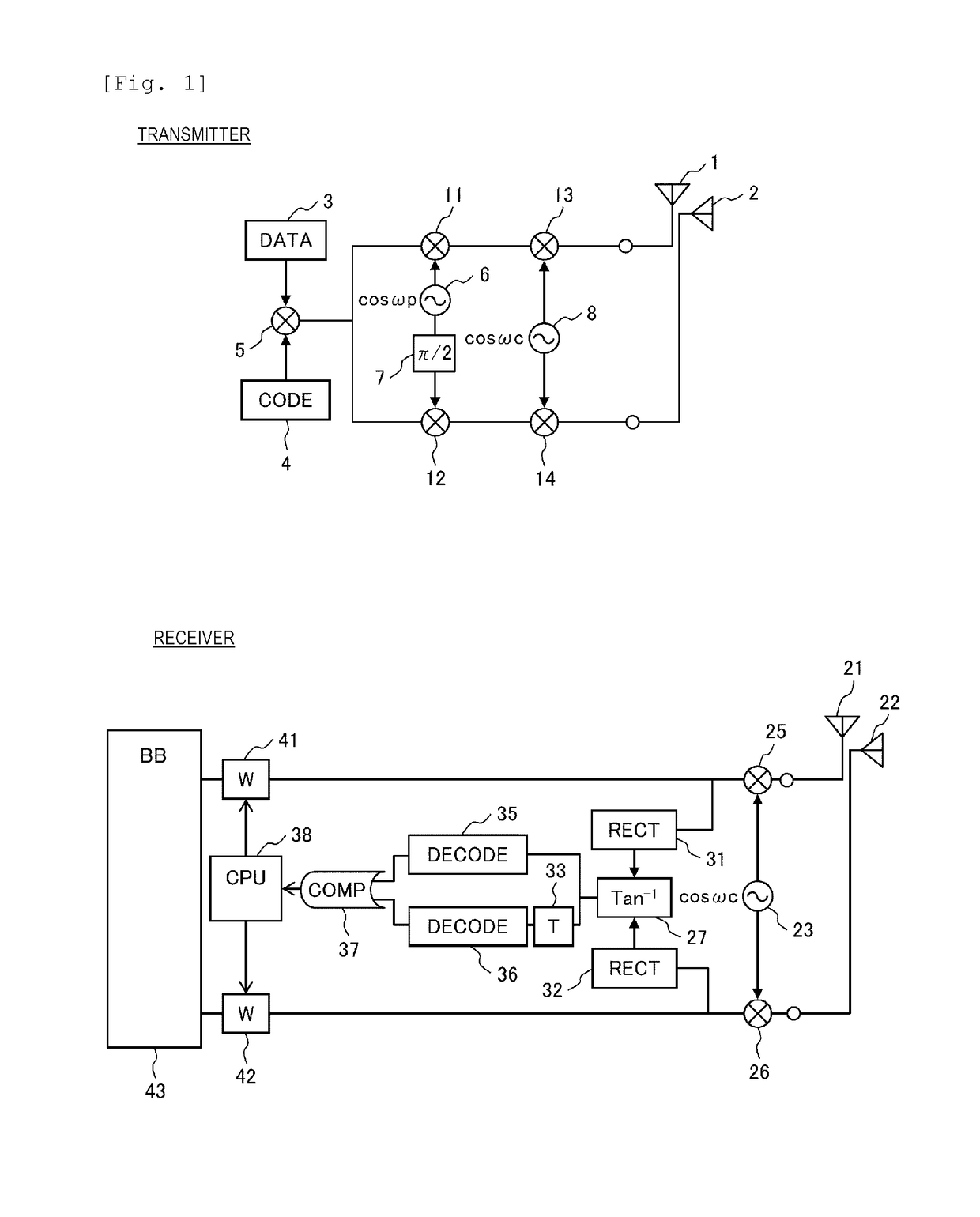
Figure 2 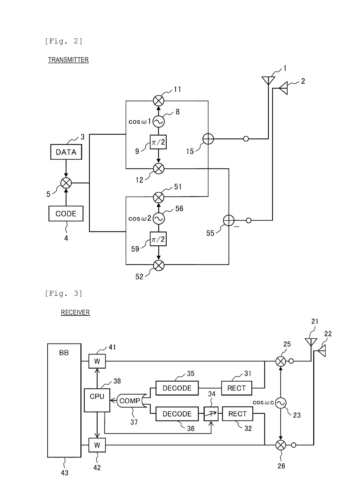
Figure 3
Abstract
Description
TECHNICAL FIELD
[0001] The present invention relates to a wireless communication system that performs communication using a radio signal between a transmitter and a receiver.BACKGROUND ART
[0002] Power plants, water purification plants, and oil refineries that are lifelines as a base of social life, and power transmission and distribution systems, water distribution systems and transportation systems associated therewith are required to be worldwide enhanced with the population growth and the improvement of a standard of living. In order to cope with such a situation, various equipment that becomes the lifeline becomes large in size, and the number of power generation equipment, water purification equipment, oil refining equipment, substation equipment, water distribution equipment, or pipelines steadily increases in individual systems or individual plant. For efficient operation of the system or the plant and ensuring of safety, a need for technology for coupling individual equipment t...
Examples
embodiment 1
[0033]FIG. 1 illustrates a configuration diagram of a wireless communication system according to Embodiment 1 of the present invention.
[0034]A transmitter includes a digital data generation circuit (DATA) 3, and a transmission polarization angle identification code generation circuit (CODE) 4. A polarization angle identification code output from the transmission polarization angle identification code generation circuit 4 is superimposed on digital data output from the digital data generation circuit 3 by a first transmission multiplier 5, and an output thereof is branched in two. A first branch of the output of the first transmission multiplier 5 is multiplied by the output of the polarization rotation frequency generation circuit 6 by a second transmission multiplier 11, and a result thereof, that is, an output of the second transmission multiplier 11 is multiplied by an output (Frequency: ωc) of a transmission carrier frequency generation circuit 8 by a third transmission multipli...
embodiment 2
[0046]FIG. 2 illustrates a configuration diagram of a transmitter in a wireless communication system that is Embodiment 2 of the present invention. A receiver is the same as that in any one of Embodiment 1, and Embodiments 3, 5, 7, and 9 to be described below.
[0047]The transmitter includes a digital data generation circuit 3 and a transmission polarization angle identification code generation circuit 4. A polarization angle identification code output from the transmission polarization angle identification code generation circuit (CODE) 4 is superimposed on digital data output from the digital data generation circuit (DATA) 3 by a first transmission multiplier 5, and an output thereof is branched in two.
[0048]A first branch of the output of the first transmission multiplier 5 is further branched in two, one of the branches is multiplied by an output (frequency: ω1) of a first transmission carrier frequency generation circuit 8 by a second transmission multiplier 11, and a result ther...
embodiment 3
[0053]FIG. 3 illustrates a configuration diagram of a receiver in a wireless communication system that is Embodiment 3 of the present invention. A transmitter is the same as that in any one of Embodiments 1 and 2 and Embodiments 4, 6, and 8 to be described below.
[0054]The receiver includes a first reception antenna 21, and a second reception antenna 22 spatially orthogonal to the first reception antenna 21, and an output of the first reception antenna 21 is multiplied by an output (Frequency: ωc) of a reception carrier frequency generation circuit 23 by a first reception multiplier 25, a resultant signal is branched in two, a first branch is input to a first detection circuit (RECT) 31, and a second branch is input to a first weighting circuit (W) 41. An output of the second reception antenna 22 is multiplied by the output of the reception carrier frequency generation circuit 23 by a second reception multiplier 26, a resultant is branched in two, a first branch is input to a second ...