
Multi-axis trick-cycle turbine engine & methods
The Trick-Cycle Turbine Engine addresses inefficiencies in traditional ICEs by utilizing a multi-axis rotor assembly with advanced thermal management and sealing systems, achieving 69% BTE and high power density, surpassing both traditional ICEs and electric vehicles in efficiency and emissions.
Patent Information
- Application Number
- PCT/IB2024/000770
- Authority / Receiving Office
- WO · WO
- Patent Type
- Applications
- Current Assignee / Owner
- Priority Date
- 2023-12-04
- Filing Date
- 2024-12-04
- Publication Date
- 2025-07-03
AI Technical Summary
Existing internal combustion engines (ICEs) face limitations in efficiency, power density, and environmental impact, with conventional designs struggling to overcome intrinsic flaws such as reciprocating and oscillating masses, high friction, and inefficient thermal management, while electric vehicles face challenges in energy consumption and infrastructure requirements.
The Trick-Cycle Turbine Engine employs a multi-axis rotor assembly with distinct master and slave rotors, incorporating features like intermeshing chambers, centrifugal filtration, and a 6-stage exhaust cycle to achieve high cycling speeds, efficient thermal management, and reduced friction, along with modular design and advanced sealing systems to enhance power density and efficiency.
The engine achieves a projected Brake Thermal Efficiency (BTE) of 69% with high power density, reduced emissions, and lower environmental impact, outperforming both traditional ICEs and electric vehicles in terms of energy efficiency and emissions.
Smart Images

Figure IMGF000019_0001 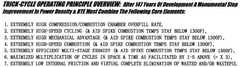
Figure IMGF000019_0002 
Figure IMGF000020_0001
Abstract
Description
[0001] BACKGROUND:
[0002] 'rhe Wankel Rotary Engine held out the promise of a fundamental improvement over the reciprocating piston type IC engine. It seemed counter intuitive, engineering: wise, that a rotary IC engine would-be less reliable, less efficient and less?enviionBtentalIy compatible than a piston type IC engine. Yet, that is the proven reality. The dream of making the Wankel what it promised to be led to an enormous effort by thousands of engineers o ver 6+ decades at enormous cost that proved unable to overcome intrinsic flaws in the operational Wankel design leading to it being removed from mass production in 2016.
[0003] The enormous effort and financial investment into the Wnkel type engine is indicative of a core understanding of the societal importance and the extremely high potential financial rewards from the discovery of a truly useful and practical substantially superior IC engine design. The need for such a discovery is perhaps even greater today than in the past. So, the quest continues.
[0004] The so-called “Liquid Piston'* is currently being developed in the US with the aid of government funding. It is simply an inverted Wankel. Afterdecades of work and many prototypes built and'tcsted at axost of millions of dollars there is still no published performance, efficiency, emissions or sustained reliability data representing an improvement over conventional ICEs in production. The same or very similar intrinsic flaws of the Wankel limit the potential of the Liquid Piston and many other attempts like it. This is entirely ascertainable without building a prototype because of the enormous amount of real-world data accumulated on the Wankel type engine.
[0005] The subject of this disclosure represents another quest for a truly better IC Engine design in the positive displacement turbine ^category that nonetheless distinguishes itself from many others by combining the elimination of alfreciprocating, oscillating or elliptical mass with simultaneous high cycling speed about four (4) times the speed of a typical 4-cycle ICE and six (6) times the Wankel, Liquid Piston & the Riley idea. Such a design would seem, at first glace, to present a veryhigh potential for fundamental & useful improvement in the very high utility, foot intrinsically inefficient, ICfoston and / or Wankel Engine concept.
[0006] Environmental concerns weather real or real but exaggerated forpolitical effect have led to a worldwide push to replace ICE powered vehicles of all types with electric motor power.
[0007] Besides being costly, impractical and even impossible in many cases, electric motor power is not as environmentally compatible as first contemplated, On average the amount of carbon energy (apox 48% less than total energy) to build, distribute, accommodate ;(due to increased weight and kick of refueling infrastructure), power, maintain, dismantle & dispose of an EV over a life cycle of 15 years and 200K mi in all climates is actual!) slightly more than that of the average of the same category of ICE powered vehicle with regenerative braking aside from other unique EV environmental issues. This is the disappointing result despite the fact that the EV motors have a; gross BTE over 90% while the ICEV engines have a gross BTE under 35%. Therefore, any new
[0008] ICE operating principle that could increase its BTE to over 50% and combine that with extremely
[0009] ?high specific power density & regenerative braking would substantially surpass the EV even with a doubling of batery density which would only improve EV (not BTE) efficiency by fol 0%. Other factors would make such an improved ICE much more environmentally friendly aside from the ability io use Hydrogen as a flex fuel and tirop unwanted emissions to ZERO and all at a fraction of the end cost which would ensure adoption and actual use by the free market (where every $5 K discount doubles the market penetration potential) which is the only way actual environmental improvements can aid will be made. It is to this new reality that the discovery of an actual breakthrough ICE operating principle is contemporaneously needed. After 147 years ft is now clear that the only way to get past the hard limits of pistons, poppet wives & secondary lever / crank action is to find an engine operating principle that eliminates^!! three (3). Since the Wankel ultimately failed to produce a better useful result even while eliminating both piftons,& poppet valves^ (but not secondary leveifcrank action) many have simply concluded that such simplification combined with actual cycling improvements is not possible and have focused on either continued improvement in standard and current production ICE designs OR electrification. Therefore, the art record of serious attempts to eliminate all three (3) ICE limiting parameters is very sparse to date.
[0010] The invention disclosed by O’Connor (US 9,103,210) entitled “Rotary Device” is a dual axis turbine which attempts to become a simple two (2) rotor engine. It is (perhaps) the first publicly disclosed attempt to eliminate all three(3) Itafting / fectors in an IC engine operating principle.
[0011] The “Omega One” as disclosed by Riley (US 11,384,684 & US 11,788,462) is in feet a dual axis turbine design. The Riley design requires only four (4) rotors (plus timing gears) to complete 4-cycles per revolution. However, the Riley disclosure reveals major inherent cycle timing, sealing, speed limitation and efficiency issues that raise concerns as to its ability to produce any useful work. Therefore, predictably even after several sophisticated prototypes have been produced and years of effort there is no indication of the Omega 1 producing a single self-sustained motoring event.
[0012] The subject of this disclosure represents, to date, the most serious and .promising quest for a truly beter IC engine design in the rare positive displacement turbine category. The herein disclosure distinguishes itself from Wankel, O’Connor & Riley in multiple key identifiers completely sol ving all the inherent issues thereof e ven while allowing for superior combustion and cycle operational control & timing & foel flexibility.
[0013] DESCRIPTION: QFJNVENTION:
[0014] (SEE 32-page TRICK CYCLE TURBME\doc;attached;and figures 1-19)
[0015] 1. ENGINE TYPE DEFIMTION:
[0016] Any engine that has a main power shaft (See "Spec & Tec h as part of the drawings) that rotates free from any secondary lever / crank action and is not in connection with any other shaft Which is controlled by motion defined as a lever / crank action, is a turbine. The here disclosed positive displacement turbine is a non-traditionai ty pe of turbine that does not have any of the drawbacks common to traditional turbines such as lack of instant start, instant torque and instant power and speed regulation capabilities, Etc.
[0017] 2. MULTI-AXIS TRICK-CYCLE TURBINE ENOINE BASIC FUNCTION (Claimed priority date as mostly covered in Provisional Patent Application No. 63 / 629,847 dated 12 / 04 / 2023);
[0018] The Trick-Cvcle Turbine is a multiple axis turbine configuration where one preferred embodiment is illustrated in Fig, L
[0019] At its core the engine disclosed herein is a sealable intenneshing multi-axis rotor assembly(Figs. 2). There is at least one master rotor and at least one slave rotor. The master rotor has a series of chambers cut into its outer circumference, preferably at least three (3) and no more than four (4), that act as compression & combustion or expansion chambers upon counter rotation of .master to slave rotor. The slave rotors have corresponding tomahawk ax shaped cogs that intermesh with the master rotor chambers (pigs. 3-5) in locked timing to create a constant reoccurring series of seated chambers with descending followed by ascending volume events therein upon counter rotation of both rotors (Figs. 3-5). The series of descending & ascending volume events adequate to compress a Working fluid for that purpose alone and / or for igniting a sub portion of injected fuel to affect rapid expansion of the working fluid to create an expansion cycle adequate to convert a portion of the resultant expansion thereof into useful mechanfeal work as a turbine after effect.
[0020] A multi-axis turbine engine in which the master and slave rotors must be distinctly different to fonction as a proper engine as-intended is inherently distinct from O’Connor in which all rotors are essentially identical by design.
[0021] Preferred Embodiments:
[0022] A. The turbines are arranged with at least two (2) master (or core) turbines each with at least one (1) slave turbine. One set of master & slave turbines controls and enables induction and projection of the initially ingested working fluid, and the other set affects compression, expansion & exhaust distinct from O’Connor & fUley. Each of the turbines have at least one protrusion on its outer circumference and / or at least one corresponding relief as depicted in Figs. 2-8.
[0023] Separating the function of the turbine assemblies allows for substantially improved function of all four (4) cycles including reduction to elimination of exhaust / intake overlap with substantially increased flow capacity and improved thermal control and distribution among other advantages including affecting wnservation of thermal energy.
[0024] B. At least one (1) slave turbine is tasked to perform the compression and expansion (power) cycles and at least one (1 ) other slave turbine is tasked to perform the exhaust and intake cycles acting on one (1) master rotor distinct from Riley aid completing foil positive displacement 4^cycle function without any reciprocating, elliptical or osculating mass.
[0025] Separating the function of the slave turbines allows for substantially improved function of all four (4) cycles including reduction to elimination of exhaust / intake overlap with substantially increased flow capacity and improved thermal control and distribution among other advantages including affecting conservation of thermal energy.
[0026] C. As depicted in Fig. I the most preferred version of “B5* is the use of four (4) total slave turbines allows for perfect balance where whatever action occurs on one side of the engine is perfectly duplicated on the other reducing loading on the main bearings and promoting power smoothness. It also allows for more cycles to be completed per revolution increasing power density.
[0027] D. In the most preferred embodiment two sets of master <fc slave rotors work in tandem and split functions. The first set control induction and projection of the initial working fluid to the second set of master & slave rotors which control the compression, expansion and exhaust cycles (Figs. 2-8), which is distinct from Riley and is accomplished in a manner distinct form that anticipated by O’Connor.
[0028] In this embodiment the first set of rotors can be arranged to act as a select-able fully integrated positive pressure compressor or supercharger (Fig. 7). The throttle assembly can easily be located in-between the first & second set of rotor assemblies (Fig. 16) which provides several advantages including the ability at affect and control fester warm up of the induction charge and the entire engine in cold conditions and such an arrangement is more compact than the application of external throttle bodies and is distinct from that anticipated from O’Connor and from Riley in particular because such an arrangement would not work on the Omega 1.
[0029] E. The most preferred embodiment of “D” is one in which the tandem set of split function master & slave rotors includes three (3) slave rotors each as depicted in fig. 2.
[0030] 3. 2-STAGE CHARGE BOOST SYSTEM:
[0031] In preferred embodiment 2E a series of impeller screw blades affixed around a center length shaft is mounted within hollow center hubs as depicted in Fig. 7. The impellers are arranged so they push working fluid into the hub toward the center from both ends simultaneously creating positive pressure directly in the center of the hollow hub. The splined hollow hubs have a select number of ports machined into its center length as depicted in Fig. 8. This creates a flow path for the pressurized working fluid to flow out from the hub and into the slave compressor rotor assembly equipped with internal ports that run from its center to and through the of the slave compressor rotor ’s cogs as depicted in Fig. 7. The pressurized working fluid is thereby able to flow through corresponding ports in the master compressor rotor assembly where it is then able to pressurize the central internal engine manifold ahead of the throttle plate as depicted in Fig. 16.
[0032] In this way the slave hub assemblies are able to double as match speed centrifugal super chargers producing just slightly above atmospheric pressure @ low speeds and moderate boost of 2-4 p>i a high speeds.
[0033] This is stage one (1) boost.
[0034] Aset of ring valves are provided as depicted in Fig 15 (See also “Spec & Tech” page No. 31). When these valves are rotated into the full boost position, they generate a unidirectional flow volume greater than the flow from the centrifugal super chargers alone and greater than the reference volume of the power rotor system in order to aflecta very efficientpositive displacement charge boost thereof
[0035] This is stage two (2) boost.
[0036] Since this all occurs internally it is very efficient and quite compared to other forms of supercharging. Further, the ring valve system allows for complete control adjustments instantly on the fly. There is no need for blow off valves where pumping work is wasted because it is able to affect full bypass where all positive displacement work is completely removed, and the working fluid is able to flow straight through to the central manifold with no effective obstruction. Boost can then be feathered in as lightly or boldly «s need be so the .system never performs needless pumping work. None of this is anticipated by Wankel. O'Connor. Ri lex or anyone else known at this time.
[0037] A. Centrifugal Filtration & Water Separator’
[0038] The system also provides the perfect means to remove dust from the working fluid by means of centrifugal force. First, having a large over supply of air available through six (6) centri fugal chargers the air never needs to travel into the system at a high rate of speed. This gives the centrifugal forces plenty of time to separate any heavier than air particles and push them out before they can enter the engine and do any damage.
[0039] The same system will also protect against excessive water entering then engine when running and lave the effect ofcleaning the dirt filtration system at the same time.
[0040] 4. SECONDARY IN-CHAIN COMPRESSION BOOST CHAMBERS:
[0041] To the extent that some of the preferred embodiments described above can generate a natural positive displacement intake cycle, the sealable, intermeshing;rotor;arrangement described herein would limit the compression ratio (CR) of the working fluid to approximately 9:1. In this context a 9:1 CR is high enough 4o produce power density and BTE above current ICE levels but also represents a calculable compromise from peak potential of the system. Therefore, in the preferred embodiments a secondary in-chain compression boost chamber is cut into the outer periphery of the master rotor just in front of the primary compression / combustion chamber (Fig. 17). The slave rotors are equipped with special shaped cog that takes on the shape of a bear claw (Fig. 17). As it intermeshes with the master rotor it displaces working fluid forward pre-pressurizing the primary compression / combustion chamber which has the effect of boosting the otherwise naturally limited ( R to a potential of 14: 1 or higher. 5. CHAIN REACTION DUAL EXPANSION CHAMBER:
[0042] The secondary in-chain compression boost chamber provides the opportunity to add the function as a chain reaction combustion / expansion chamber and further boost both power density and BTE and to lower emissions especially when most liquid fuels are used.
[0043] 6. PRESSURE PROFIEE / MATCHING ^ SEALING:
[0044] Preferred Embodiment 2E is further preferred because of its important and unique capability to create an identical pressure profile in all secondary and primary master rotor compression / expansion chambers @ the exact same time.
[0045] In all other known rotary and positive displacement type turbine engines there are four (4) main factors that make sealing these types of engines particularly challenging:
[0046] A. High pressure chambers are surrounded by low pressure chambers at the same time,
[0047] B. a short physical distance between the high & low pressure chambers,
[0048] C. uneven heat distribution in large part due to A & B,
[0049] D. long cycle time.
[0050] Factors A-D are all paramount to the design of Wankel & Riley and factors A-C apply to O’Connor. None of these factors apply to the here disclosed Trick-Cycle Turbine in the preferred arrangement 2 E.
[0051] 7. 6-STAGE EXHAUST CYCLE & DRAFT EXHAUST CYCLE:
[0052] As depicted in Fig. 17 the preferred embodiment 2E is further preferred due to the unique ability to create a highly efficient d-stage exhaust cycle (See “SPEC & TECH” page 8) by directing exhaust gases back into the slave rotor housing strategically rather than directly to atmosphere or a turbo charger (See “SPEC & TECH” page 10 & 13). As the bear claw & tomahawk cogs leave their respective chambers and enter the slave rotor housing, multiple chambers open up in front and behind these cogs. This allows for exhaust gases to convert their speed & heat into turbo work recovered directly back into the system before it has time to lose heat or momentum and do so without any back pressure tosses associated with all other engine turbos. The Tomahawk cog passing by the transfer exhaust port acts as a perfect valve turning off & on the exhaust flow as needed and timed for maximum positive effect.
[0053] Once the exhaust gases are trapped in the slave rotor chambers a draft cycle occurs where the gases are allowed to aid in spreading heat more evenly around the relatively cool slave housing portion of the engine. This aids in engine warm-up, maintaining tight tolerances through warm up to further aidin consistent sealing, AND, reduces the need for bulky sound atenuation equipment.
[0054] Still further, this system creates an ideal opportunity to affect an afterburner cycle which in certain conditions can significantly increase power density & BTE and lower emissions.
[0055] All of this is not anticipated by and otherwise is distinct from Wankel, O’Connor, Riley & many others.
[0056] 8. MESH ROTOR SEALING:
[0057] One of the issues is how to allow the two (2) stacked rotor faces to lightly touch to seal when cold and yet not bind when they expand due to heat. This problem is further complicated by the large disparity between the peak temperature reached by the expansion / exhaust or power rotor compared to the intake / compression rotor. Part of that problem can possibly be mitigated by using different materials for each with different thermal expansion ratios such as titanium for the power rotor and aluminum for the cooler running intake and compression rotor. But that will not help the former mentioned issue. For that issue a very shallow solid apex mesh arrangement is proposed as shown on a different type of rotor for another engine (Fig. 19). Since the rotors relational movement is synchronized by a gear set then this arrangement will break in to virtually zero (0) friction but will allow for thermal expansion & contraction without binding and yet create a more perfect seal between the two (2) faces at all temperatures.
[0058] A further refinement is to form a double helix pattern arranged to push air within the square cogs to the outside as depicted in Fig. 19.
[0059] With the use of hard low friction surfaces such as hard anodize or Titanium Nitride (TiN) coatings (Fig. 19) and where liquid fuel is used and carbon is produced it may be possible to allow this mesh sealing system to double as a timing gear system and reduce weight, size & cost In such ease the load bearing output shaft would be exclusively derived directly from the expansion cycle or power rotor so the load on these integrated rotor gears would be reduced to only that that produced by the compression cycle, turbo exhaust and part time afterburner cycle all of produce a fraction of the main power cycle load greatly reducing friction and increasing the life of the sy stem . Such a system would not be expected to have an extended longevity compared to a typical OEM standard, but, for applications where cost and / or weight & size are at higher premium than super long life such as in certain racing, motorcycle & sport marine applications this could be a viable alternative.
[0060] 9. TIMING GEARS’
[0061] A. Three (3) timing gears with half speed center gear = slower gear teeth speed and provide half speed center gear for dual coil trigger setup for super high-energy high-speed spark ignition, AND B. captured grease timing gears eliminates need for oil exposed to combustion contamination and vice-versa B eliminates need for oil pump, oil reservoir and regular oil changes.
[0062] 10. IGNITION SYSTEMS:
[0063] A. spark = dual fire half time gear trigger = 3 timing gears with half time center gear -slowdown all gear teeth speed and provide half speed center gear for dual coil trigger setup for super high- energy high-speed spark ignition,
[0064] B. glow plug,
[0065] G. auto ignition as controlled through combination exhaust flow control valve for manipulating EG R as 1 xhaust ( ias Capture ( H iC ) on the fix (See "SPIT X- I ECI I" page 10 & 13 ). AND
[0066] D. Homogeneous Charge Compression Ignition (HCCI) as aided by hot vapor induced "by using the intake charge to cool the expansion chamber.
[0067] 11. SEALING:
[0068] A. Titanium for lower thermal expansion,
[0069] B. mesh rotor gear edges,
[0070] C. rotor face surface agitators (Fig. 19), AND
[0071] D. not preferred but optional dynamic seals=some that use centrifugal force some gas forces but no spring (Fig. 18).
[0072] 12. APPLICAHON OF CERAMICS:
[0073] The Trick-Cycle Turbine lends itself well ter the application of ceramics much better than a piston type ICE starting with the tomahawk cogs as shown in Fig 2:
[0074] A. Reduce heat rejection,
[0075] B. better sealing control with lower thermal expansion ratios and as a thermal barrier to reduce thermal expansion surrounding components, AND C. circular ring around square edge rotors & spherical ring around curved edge rotors.
[0076] 13. MODULAR:
[0077] The Trick-Cycle T urbine lends itself well to modular add on of additional complete power rotor assemblies w here, lor one example, a single compressor rotor assembly could made large enough to boost a power rotor assembly to each side. In such a case the power rotors could be offset so as to allow for up to three (3) simultaneous firings every 60 degrees of rotati on for a total of IS firings e\ er\ res olution.
[0078] A. Counter Rotating Power Shafts:
[0079] The modular add on provides an excellent opportunity to run a second counter rotating (or corotating) power shall through the center of the first or front power shaft (Fig. 10 No. 9). In such a case both engines would be capable of running independent of the other so in the case of counter rotating props for aircraft complicated coupling of the shafts can be eliminated with many self- evident advantages and redundancy is introduced for added safety.
[0080] 14. DEDICATED STAND-ALONE COMPRESSOR:
[0081] A. Extremely efficient intake cycle,
[0082] B volume capacity doubled for same width rotor as power rotor
[0083] C. internal transfer ports and unidirectional ring valves give added control for pressure regulation @ highest possible efficiency and lower sound levels.
[0084] D. ofifthe shelf unidirectional ck valve application for store-able compression work.
[0085] 15. COMBINATION CENTER: DRIVE SHAFT COOLING AIR TURBINE:
[0086] As depicted in Fig. 2 an improved method of use of the tubular center shaft sec tion of the Trick- Cycle Turbine Engine is proposed. The preferred method combines the function of a strong highly reinforced lightweight hoi low coupled center drive shaft with the ability to positively & efficiently displace air across enclosed combination air directional & cooling fins through a screw turbine from one end of the ungine block / housing to the; other and across corresponding enclosed air directional & cooling fins. This capability can then be tapped into for multiple purposes including but not limited to:
[0087] A. Air cooling the engine from the center, : AND
[0088] B. cool running main bearings:
[0089] The proposed and preferred design also, and very importantly, allows for double roller main bearings to be displaced at the ends of the hollow drive shaft Well away forthe engines heat source and mounted in a structure designed to dissipate heat such as may come from extremely high speeds. This ensures that the bearings can be permanent!} sealed and proper heat dissipating thin low friction synthetic oil can be constantly supplied during operation. In the preferred embodiment the hollow center shaft is partially filled with the specialbearing lubricant and a means is supplied whereby centrifugal forces can be used to constantly force the otherwise sealed away bearing lubricant into the bearing races even when running upside down. In such a case the sealed away special oil which is never exposed to contaminating liquid fuel and / or combustion gases is expected to last; beyond the projected extremely long life of the engine and should eliminate the need for regular oil changes saving down time, costs and the environment.
[0090] Still further this preferred arrangement allows for smaller diameter roller ^bearingsfo be used which have much higher speed limitations. To be able to go from a 4.5” dia bearing to a 2.5” dia doubles the speed limits from approximately 11,000 RPM to 22,000 RPM.
[0091] 16. THERMOSTATICALLY CONTROLLED FORCED AIR COOLING:
[0092] In conjunction with section 15 above a system of thermostatically controlled apertures are arranged to cut off all airflow through the screw turbine in cold start and / or when running in extremely cold air supply.
[0093] 17. CENTRIFUGAL & PRESSURE DYNAMIC FLOATING .SEALS:
[0094] One of the biggest challenges that most rotary type engines must deal with is internal sealing & separating cycles one from the other. This problem is further exacerbated when cycles take more time to complete then a typical piston type IC Engine which most rotary type engines including the Riley turbine engine does. However, The Trick-Cycle turbine cycles around four times the speed than the piston ICE and significantly six times that of Wankel <& Riley. This fact, especially combined with all the other unique capabilities disclosed herein, makes the sealing issue far less challenging than those other cases. However, thatdoes not mean there is no room for optimization.
[0095] Unlike sealing a round piston, sealing square structures is much more challenging as the experience with the Wankel has taught. Therefore, a series of centrifugal and / or pressure dynamic floating I -piece seal arrangements is proposed such as depicted in Fig. 18 which can be made of self-lubricating carbon graphite material. In a preferred embodiment the dynamic floating seal such as that depicted in Fig. 18 is mounted in various locations on the outer circumference of a rotor assembly and is designed to be gas pressure neutral, so that only centrifugal force sets the definable seal pressure towards the rapidly moving outside chamber wall / housing surface. Such a system can easily be tuned to control the precise amount of maximum seal pressure by simply adding or taking away bias weights. In this way a strong constant to near constant free flow gas barrier and no to low contact gas seal can be created that automatically adjusts to changes in the gap due to thermal expansion factors or uneven machined surfaces. Etc. This is only as an optional optimization factor as it is foreseeable that the Trick-Cycle turbine will be able to produce record levels of both power density & BTE without any active light contact to no contact gas seals.
[0096] A. Simple Dynamic Sealing; Another way to lower friction and allo w for break-in to very tight tolerances is the use of rotor face and / or edge surface agitators such as the that depicted in Fig. 19. In such a case the preferred method is to curve them away:fi»m the:rotationaldirectton so as to force any working fluid bypass to the outside to create a jam gas seal effect but also to recoup some of the energy lost with any sudden momentary or cyclic bypass as it would only add to the turbine effect returning much of that energy back to the system.
[0097] 18. INTEGRAfED EXHAUST -CATALYST:
[0098] In a preferred arrangement exhaust after-treatment catalyst is integrated within the proper housing around the outer periphery of the expansion - draft - exhaust cycle chamber and placed so that exhaust gases are forced into contact directly after the expansion cycle switches to the exhaust draft cycle. Centrifugal force of the spinning rotor during the exhaust draft cycle and / or positive displacement exhaust cycle will fling any un-bumed fuel molecules forcefully into the catalyst where it can be consumed by the catalyst and converted to exhaust gas constituents before exiting one or both exhaust ports. With a dual exhaust port / valves one port / valve can be situated to force all the exhaust flow through it past all or a major portion of the catalyst. In this way with two (2) exhaust flow control valves, integrated after-treatment can be selected as optional and / or situational and or blended as need be and can be controlled by a micro-processor. Since neither O’Connor OR Riley anticipate in any manner a draft exhaust cycle than this element is distinct from both.
[0099] 20. EXPANSION CYCLE:
[0100] The Trick-Cycle Turbine provides for much improved expansion cycle dynamics including an increased Torque Arm Moment (TAM) compared to a typical ICE of the same basic volume size as detailed in the “Spec & Tech” page 24.
[0101] August 2024 NOTE: The TRICK-CYCLE TURBINE (TCT) was first conceived independentl y in November of 2020. What, fol lows is the resul t, to date, of an exhaustive multi-year feasibility study, more concentrated in the last year and focused on the TOMAHAVK TX ETTKJ version of the TCT operating principle.;
[0102] The following adheres strictly to that which can reasonably & accurately be predicted based on the laws of physics, basic principles of ICE function, computer simulation and experience.
[0103] The TOMAHAVK TX here demonstrates, among many monumental feats, that it is possible to increase the sophistication, flexibility & tunability of an ICE engine well beyond that achieved by any production engine today even while reducing the complexity, parts count & mass production cost by up to 50%+, ©ven if 20% of the motor is made up of titanium. MOTION (I. E. SECONDARY LEVER / CRANK & RECIPROCATING MOTION) INCLUDING THE ELIMINATION OF WATER AND OIL PUBS ft AID SPIKE COMBUSTION TEMPS STAY BELOW 1300F) ,
[0104] 8. HIGH-SPEED TORQUE MULTIPLICATION AS FACILITATED BY 1-7 ABOVE,
[0105] 9. PHYSICAL SPACE SEPARATION BETWEEN COMPRESSION / COMBUSTI® CHAMBERS WITH IDENTICAL SUPER HIGH SPEED PRESSURE PROFILES WHICH WHEN COMBINED WITH RECORD HI® BTE ALLOWS FOR TOLERANCES TO BE MAINTAINED IN TIGHT ENOUGH RANGES TO GREATLY REDUCE OR ELIMINATE THE NEED FOR CONSTANT CONTACT SEALS,
[0106] 10. EXTREMELY EFFICIENT 2-STAGE BOOST SYSTEM WITH 0-100% CONTROLLED BYPASS OF MAIN STAGE (2® STAGE) BY WAY OF ELIMINATION OF PUMPING WORK WITHOUT “WASTE” ,
[0107] 11. MOST EFFECTIVE AND YET SIMPLE EGR SYSTEM WORKING AS AN EXHAUST GAS CAPTURE (EGC) SYSTEM WITH FULL ACTIVE INTELLIGENT CONTROL AND VARIABILITY CAPABILITY ALLOWING FOR CONTROLLED AND SUSTAINED AUTO- I GNITION DUR ING KEY HIGH UTILITY OPERATIONAL CONDITIONS, ft AID SPIKE COMBUSTION TEMPS STAY BELOW 1300F) , AND
[0108] 12. EXTREMELY HIGH “ TNEHMAI CONSERVATION’
[0109] BTSHAGUBK Reference Displacement (= single displacement of all combustion chambers once) - . 761L (46 CID) ; actual operational swept volume = active between 2. 28L-7. 5L (over 360° rotation) & 6.84L~15L over 720° rotation relative to standard 4-cycle ICE = 915 direct comparison CID (No internal cycle speed multiplier) . wmom wumi HOH-oousn w TEBMAI MH nowcmcm = The m is
[0110] The TOMAHAWK 7X9 3 times the flow ratio could be predicted to max out in a range of 15, 000-17, 500 RPM & peak HP would land in the 16, 500-19, 000 RPM range) .
[0111] HU / NG OBOEB: = 18 firings per ''rev = 3 simultaneous firings every 60° (No internal cycle speed multiplier).
[0112] PBOJECTEOPEAKPOWEB OUTPUT: = 8700 shp @ 12, 500 RPM*
[0113] (11,500 shp @ 16,500 RPM)
[0114] PROJECTED PEAK TOBOUE OUTPUT: = 3660 ft / lb @ 12, 500 RPM*
[0115] (on 85 octane pump gas) volume to an Effocthra Swept Volume (f SV In Uters) over 72»* to 2M entf jwoducee 3M MM of torque WITHOUT nitro- proJsetSens are In fact, MRMtwHw. (SeePageW CE with instant start
[0116] & torque & with 10X+ power density can power a vehicle through a life cycle at a real -world rate ' - ■' (& total energy) ■v■ "■ ’ : soiav vohic t r pouered ny c l et i rk sacu-r-i rat vd 90 93% eff i c i ent?. , AND, no future breakthrough is physically possible that can flip that calculation back to advantage EV. Top-down hype forced conventional wisdot is actually not wise at all. mslsHrnm In automobiles / trucks ( “light ^6511®’’ ;) Real World (RW) average ICEV fuel consumption per mile (= 26 (2024-EPA) MPG X 1. 04 = 27 RW MPG) is compared to average EV energy consumpt ion per mile (91 (2024-EPA) MPGc X . 87 - 79 RW MPGe) . Source for adjustment of both: Road & Track Magazine:
[0117] “How ERA Range Figures Compare With Reality ” July 29, 2023-based on real worl d test ing of many ICEVs & EVs between 2016 & 2023. Carbon energy consumption is 100% for the ICEV and 82% (projected average mix over next 20 years) for the EV.
[0118] Life cycle comparison = 200K mi & 15 years (average age of vehicles being approximately 13 years now) .
[0119] All well extract, distribution, refining process, transmission losses. Etc. are factored for both based predominantly on credible government and industry sources.
[0120] Regenerative Braking is added to the ICE vehicles which can be easily applied at a very low cost.
[0121] EV main battery replacement is factored @ 75% average rate over 200k mi within first 15-year period based on factory recommended limited charging which diminishes range by 30% over advertised range. Full range charging = 100% replacement required. Energy consumed to build all vehicles & EV battery packs and to replace, dispose and / br recycle the same is compared & factored based predominantly on credible government &. industry sources.
[0122] Well documented Temperature sensitivity of EVs compared to ICEs is factored. Well documented EV temp sensitive & base charging; losses, sit loss and battery degradation is compared to liquid fuel evaporative losses, Etc. and are factored. Infrastructure build-out energy costs over same 15-year period (home & retail outlet) are estimated & factored.
[0123] Energy consumption to accommodate higher EV weight affecting EV distribution to dealers, tire wear, road repair, wrecking & recycling Etc, is factored based predominantly on a mix of RW data (need to build and rebuild stronger & bigger bridges & parking structures and other weight sensitive infrastructure are not factored in favoring the EV) .
[0124] The time value loss due to substantially higher refueling times for EVs estimated to increase the number of EVs needed to cover all utility needs of end users by at least 2% or more is not factored in because it more than offsets the maintenance differential to the ICEVs. Amazingly when considering all the above factors (actively suppressed by governments, biased media & affected industries) the current Real World carbon energy consumed for ICEVs AND EVs (where both have regenerative braking) is the about the same with the ICEV favored slightly ® 23 MPG to 21. 5 MPGe respectively. However, the total energy consumed favors the ICEV by another 18% with 23 MPG for the ICEV & only W MPGe for the EV.
[0125] These RW numbers illustrate how the 90-95% MAX BTE of electric motors is very misleading. Electric motors suffer significant loss in efficiency below 50% load which is where they spend the vast majority of their operational life in an EV. Regardless, it is clear that the overall higher than ICE BTE simply does not compensate for all the inherent negative factors surrounding electrification not including intractable weight. In real world terms based on the current ICE development stage electrification does not solve any issue* real or perceived, and, actually goes backwards in total environmental impact, AND, there is simply too little room left for monumental breakthroughs in electric motor design to ever change that reality.
[0126] Breakthroughs in battery design are still possible but even an extremely unlikely doubling of safe power density would only improve overall EV efficiency by 8—10%. k m Comparison: As is illustrated within thi s document achievable extremely high power density combined with high BTE across a broad range of speed and load settings is projected to be f-7 times higher than current production ICEs in the normal usable utility load range where the average light vehicle MPG is calculated (See BTE vs Load graph below) . This kind of monumental breakthrough will facilitate overall vehicle simplification a higher cost differential and a weight differential of 1800-32001bs over the EV. The combined effect of all these factors is an obtainable RW fuel economy of ' M';'- wi thout regenerat ive braking and ft with.
[0127] This means that a 3-gallon fuel tank would produce a usable range higher than any product ion EV, would weigh 35Lbs full, lake 21 seconds to refi l l, AND, get lighter as it empties. By comparison, an EV battery pack weighs 1100“20001bs takes hours to fully refill safely and weighs the same when empty. war sanw electrical source, wiiigi ityto ct’eate 1 ^tliver ft to the wehiole all while .actually^ gaiainf usable space allowini for iip-ovediaerodllaBicfj and saf ety design featsires. TBetcoiibi^ f lex rihgi
[0128] With the TfX the EV will never be able to come close to competing at ANY level, not emissions, environmental impact, cost, 0-60 MPH, % mi, top speed, range, fuel efficiency (RW or otherwise), stopping distance, safety. Etc. not even maintenance costs & time, and, that is on gasoline. Use NG or H2 as a fuel and the EV is pushed much further behind. COMPRESSION [ewansiMimiom Active between 11 ft 26:1 (1 of manyse lee table ranges). / imucnON: TWO 121 stage boost: Combination of internal ft integral match speed Centrifugal Screw Supercharge X 6 (1ststage) ft active direct internal ft integral positive displacement (2ndft main stage) (No separate dedicated induction charging system) with an effective max induction gauge pressure of 25-30 psi (1. 7— 2 bar) .
[0129] NOTE: The intelligent yet simple internal main compressor control rotary valve system allows for the compressor to be tunned perfectly on the fly to provide just the amount of boost desired without wasted pumping work. This system allows for a complete bypass where virtually no pumping work is performed. Unlike most boost systems where, even if bypass is attempted, pumping work is not eliminated but may be reduced only by pumping excess air back to atmosphere, the OF system actually reduces ft / or eliminates pumping work @ select partial or full bypass. mmON mm& The BJKMMr n is capable of breaking many world records without VVT. Nonetheless, it has certain favorable design features that make it uniquely accommodating to the application of a simple ft reliable fully active Intelligent Intake Variable Valve Timing (OTW system. The Tn Um system controls both duration and opening & closing phase angle timing instantly ft on the fly.
[0130] NOTE: The OT features direct and indirect dual semi “wraparound SS cross flow intake port / valves which are not exposed to anything close to the peak temperatures ft pressures of combustion events as in a typical ICE. The 1W system allows for the di rect cross flow to be offset selectively on the fly. The crossflow offset will increase the max flow dimension of the system and: affectively increase the intake flow event duration. But, perhaps even more importantly it will induce tremendous swirl charge motion which can be tuned for a perfect balance. It is notable that even in piston engines, while much more complicated to execute, fixed offset crossflow intake systems have been produced, tested and found to greatly increase ultimate power density.
[0131] Further, and of even greater significance, when JKKKT is combined with all the other unique intelligent capabilities of the TTX, it will be possible to flex from an effective Otto Cycle to the Atkinson Cycle at any time and for any length of time desired. It is also possible to flex to the Atkinson Cycle and then the Miller Cycle or directly to the Miller Cycle as needed or desired. Also, it will be possible to flex to full autoignition at key times and situations AND to employ extreme lean burn strategies within the context of all these monumental ft unique intelligent capabilities.
[0132] &HAUST: Six (6) stage in optimal order: 1 ft 2. Two (2) stage blow down, 3. Internal positive displacement 4. Scavenge 5. Centrifugal charge out, AND 6. External positive displacement.
[0133] NOTE: The t radi t ional ICE is p lagued wi th inherent cycle inefficienci es that facilitate the need to compromise poppet valve timing that leads to other desperate attempts to mitigate its negative effects on the high end or low end or both.
[0134] Therefore, no super tuned exhaust system for the ICE "makes power* all it can hope to achieve is to return a fractional portion of the losses from the inefficient cycle. As something closer to a perfect cyc l o comes into focus all the sizing, volume matching, pressure wave riding, velocity enhancing, anti -rovers ion, WT ft thermal management tricks ft techniques are of greatly diminished value. The T 'RICK-CYCLE operating principle as realized through the OF achieves a continuous flow exhaust cycle with modest fluctuations in pressure i f low vs the traditional IGE in which much hotter exhaust is forced to exit as short intermittent bursts at higher pressure followed by twice as much time with no flow at all. This creates wasted energy in the form of noise and it also requires a much larger piping structure as would be normally needed to service a given intake flow & combustion dimension which increases bulk, weight & cost and complicates heat management.
[0135] FOElSfSTU: Combination of direct & indirect EFI all © low pressure (40
[0136] 120 psi). 18 direct injectors (6 low flow & 12 high flow) . Direct injectors . , , will likely be incorporated in liquid fuel injection applications under license from Reggie D. Huff & XCENTRICK INNOVATIONS Ltd.
[0137] NOTE: The fuel rai l mount system doubles as a strategic heat s ink in service to the “CHILL ZONES” as described in the section below.
[0138] WNmON: Inductive shaft trigger' direct & selective HGCI (auto-ignition) .
[0139] SffSfKPIUgS: Modified racing with three (3) palatium clad ground electrodes and an iridium center electrode = four (4) per to accommodate the Intelligent Intake alve
[0140] Variable Timing (IIVVT) system. Inductive Coils: All spark plugs arc fired by 12 quad secondary windi ng loop dual fire compact coi l packs wi th ful l alternating & true mul ti-spark oeHn^tiieSpnitienemtiattie:
[0141] Combustion Chamber : Fully ad justable between 60 & 240kv up to 16, 500 60 - 80kv single spark, 120-160kv double spark & 180~240kv triple spark) .
[0142] Fully adjustable between 48 & 190kv © 20, 000+ RPM(= 48 - 64kv single spark, 96~128kv double spark & 144-190kv triple spark) . Afterburner Chamber: Fully adjustable between 60 & 160kv up to 16, 500 RPM(= 60~80kv single spark & 120-160kv double spark).
[0143] Fully adjustable between 48 & 128kv @ 20, 000+ RPM RPM(= 48 - 64kv single spark & 96-128kv double spark) .
[0144] NOTE: Due to the system * s extremely high-speed cycling The TOMAHAWK IX is uniquely qualified to potentially utilize and perfect HCCI auto- ignition under higher load and speed conditions unlike any ICE cycling system known. This is in part because there is a greatly reduced time between the au to~i gni t i on po in t and minimum volume -and the optimal torque arm moment point (See also “EGR / EGC System® below) . This is also why 85 Octane regular gasoline and / or hydrogen is expected to do well even in conditions of effective high CR & load. In HCCI mode the electronic ignition system can be shut off for max efficiency apart from the afterburner system which may be selectively run in combination where more peak power and high load emission control is desired or needed.
[0145] C00UM6 / WMM UP SYSTEMS: Thermostatically controlled air cooled with fully integrated central cooling turbo & no external fans. The system has a secondary function to act as an air-to-air intercooler during periods of high effective boost loading. This system in conjunction with the FI heat sink mount system & other integrated heat exchange design structures can be easily adapted to affect enhanced focused chill in the corresponding block sections encompassing the “CHILL ZONES” of the power ring assembly as described in the “ TKBMU eOMSEmnr section below.
[0146] NOTE: High BTE efficiency up to 69% = low probability of obtaining proper warm up under start-up & low loads in cold conditions. Therefore, The TOMAHAWKTX is designed with this challenge in mind. Two (2) Throttles are located deep in the center of the engine for several reasons, one being the ability to control air flow' into the- combustion chambers post compressor. During periods of start-up & warm up, idle and low loads, manifold pressure can be selectively increased even while speed and load are under complete control. The higher manifold pressure forces the engine to silently work a little harder and part of that added energy warms the manifold air instantly improving combustion efficiency and reliability while lowering cold start emissions upon start-up. a 50-66% reduction in heat rejection with a heat distribut ion factor more even from front to back, side to side & top to bottom than any other ICE design known. UKMSSKnt EGR possible. features a unique active Intelligent Exhaust Gas Capture system with a capture control range of ZERO (0) to 100%.
[0147] NOTE: Bile the TU is capable of recirculating exhaust gases by means of a straightforward EGR valve system in which exhaust gases are pumped out of the combustion chamber and then a select portion is pumped (recirculated) back into the combustion chamber an Exhaust Gas Capture (EGC) system is far superior, when possible, for several reasons. As contemplated over three (3) years ago the TTX is uniquely wel l suited to make ful l use of an EGC system & method. In an EGC system exhaust gases arc port ioned out in each cycle allowing a select portion to remain captured in the combustion chamber rather than being portioned back in. A small amount of fresh air & fuel is metered in and the captured EG fills the remaining space allowing for high CR to be maintained and greatly reducing low load negative pumping losses. The J7IEGC system will measurably reduce part load negative pumping losses by a minimum of 96% to as high as 99. 5% all while not increasing mechanical stress, friction ft / or noise such as is common to the Diesel Cycle. The TTX use system utilizes a specially designed constantly electronically variable static rotary exhaust flow control valve. This valve is not exposed to the extreme pressure and heat associated with most exhaust valves. This fact, as well as others, allows for the proprietary design of an IEGC system to facilitate a high level of sophistication of operation increasing both performance 1 efficiency 8 all loads & speeds that belies its reliable simplicity & elegance. The TH 1EGC system allows for effective VVT and yet is simpler than a comparable EGR system. In combination with the elegant & simple complete active & intelligent compressor control system the TTX will be able to make full use of low temp lean burn auto-ignition strategies across a broad range of operating conditions AID be able to adjust instantly to flex to a broad range of fuels. This is a very important aspect of the development of the / HT because it allows i t to achieve @ or near peak BTE © al l loads & speeds in contrast to al l other types of IC engines as i llustrated in the graph. This means that for applications that operate in constantly varying load ft speed conditions the actual real world efficiency gains will be significantly higher than a simple comparison of the peak BTEs would indicate.
[0148] It would also mean that the gap between city ft highway EP A fuel consumption ratings, for example, would close by 50% or more. Such a reality would make the cost, weight, complexity and maintenance of regenerative braking systems a less practical method of improving vehicle efficiency giving more flexibility to auto manufacturers to exceed all performance ft efficiency goals cost effectively, in fact © an overall cost savings.
[0149] NOTE? in February of 2022 The Mazda Corporation published a patent application 0.3. patent (US 2022 003^265 Al ’, in which a similar method is disclosed for use in a supercharged 2 stroke piston engine. It is projected that the method will allow for auto-ignition to be employed @ lbw loads and that it could increase part toad BTE to as high as 50%, However, because the Mazda system involves the use of reciprocating poppet salves, speed is limited to the 4-4500 RPM range which will greatly reduce the power density potential. Further, it will be very complicated and difficult to control the poppet valve EGC system over a broad range of speed, load & atmospheric conditions because it necessitates a complex variable poppet salve timing system to meter the EGC actively on the fly. The Mazda system also requires a high cost, complex & high maintenance extreme high pressure Direct Injecton (DI) fuel system operating © pressures exceeding 700 bar or 10,000 PSI. oomusm cmtsa soNsmm.- Semi “ceramic with Titanium with full ceramic potential* Both configurations with part time exposed spark plugs. hOTE ' Mass production of fully \ < enclosed ceramic combustion chambers is very desirable for many reasons. Much research has been dedicated to the subject.
[0150] Unfortunately, it has proven to be unattainable in terms of acceptable reliability & cost for any piston or rotary type engine, Such constraints do not apply to the TfX, The unique design features of the IW allow it to accommodate the reliable & low-cost application of ceramics in a highly effective thickness range from .318-. 84” (8-21mm) . This allows the Of to easily achieved a combustion chamber which is 77. 5% ceramic @ TDC (minimal volume) and 81.5% ceramic 8 peak effective pressure angle. A slightly more challenging but very feasible application of ceramics can increase those #s to 96% ceramic @ TDC (minimal volume) and 100% 9 peak effective pressure angle, Therefore, the JW can achieve a full ceramic enclosed pyro-yield box combustion chamber unl ike any engine design in use or contemplated today. I t is projected that such a chamber will push the BTE over 70%. The implications for thermal management are also significant.
[0151] NOTE: In both cases 2 spark plugs can be arranged to be covered from approximately 9-12® ATDC & all 4 from approximately 18-24°ATDC through the peak effective pressure angle and thereafter ensuring that they will not overheat due to the low thermal conductivity of the sufrounding ceramic material. nam eoKSBmumj:
[0152] Gross Expansion Ratio vs Ret Expansion Ratio: relatively cool air encounters a much hotter solid or liquid surface heat t ransfer i s instantaneous and therefore the air (or gas) expands instantaneously. Carefully placing boiling hot water in a 2L pop bottle capping and then shaking will accelerate the heat transfer from the hot water to the air and the bottle will become instantly pressurized. Attempt to unscrew the cap before it cools, and it will be propelled with great force in the opposite direction of the bottle top. This is a physical demonstration of a simple expansion cycle whereas in an IGE the temperature differentials are generally much greater.
[0153] Hot internal surfaces in any ICE reduces the thermal differential to the much hotter combustion gases which in turn reduces the rate of heat rejection to those surfaces. These same hot surfaces can aid in phase change of liquid fuels to vapor which instantaneously multiplies the fuel volume approximately seven (7) times but also cools & partially condenses the air charge at the same time. The resulting homogeneous charge mixture improvement in combustion performance is part of the reason warm engines start easier &. are more efficient than cold ones.
[0154] However, these same hot surfaces generate pre-expansion work starting before the induction charge reaches the intake valve and increases throughout the induction cycle which lowers Volumetric Efficiency (VE) . Swirl & tumble only make the condition worse (like shaking up the hot water bottle) however improvements in combustion efficiency caused by swirl & tumble may more than compensate. The pre-expansion work then accelerates throughout the compression cycle generating measurable negative work which, without significant control of heat, will inevitably lead to pre-ignit ion where so much negative work is produced catastrophic engine failure is possible.
[0155] ICE pre-expansion or Thermal Waste (TW) is a major limiting factor. For example, even if pre-expansion could be limited to only 101 of the gross expansion potential of a given cycle over 360° + of crank rotation that results in a 21% drop in net expansion work available. This directly corelates to a 211 increase in the fuel needed to service a given load. The reality is that under most operating conditions TW or is higher than 10%. This condition is greatly worsened with charge boosting. As much as 40% of the fuel consumed is due to the inability of the ICE to effect mtmu CONSKWION (TO. In other words where normal waste heat is recycled ft timed to aid ft boost the expansion cycle father than work against it.
[0156] This inherent double shot Thermal Waste phenomenon greatly inhibits the otherwise advantageous thermal characteristics of advanced ceramics to increase BTE as it becomes much like a dog chasing its tail. neW'Mci’iBirsi &, foremost, The TJX cycles 4 times faster than a typical ICE and 6 t imes faster than a Wankel Rotary. Thi s moans that there is far less time for pre-expansion to occur. Still further, the standard hi- performance 4-cycle ICE has a combined intake ft compression cycle time ratio to the expansion cycle of around 3, 33il. The TTX has around a 2: 1 ratio meaning it has 40% less time to affect TW based on cycle dynamics alone. When combined with the higher cycle speed this equals an 85% reduction in TW.
[0157] 2ndly, The TW performs a neat trick in which 60% of the total combustion gas heat ft pressure exposed chamber surface area is swapped out for cool surfaces that are always insolated from virtually all the heat & pressure in the expansion (combustion) cycle. 20% of the combustion gas heat and pressure exposed surface area (in the form of the ceramic Tomahawks) spends 300° rotating well away from the heat source and temporarily cooling the outer peripheral surface before reentering the combustion chamber for the compression cycle. During the expansion cycle the reserve heat stored in the Tomahawks inhibits heat rejection.
[0158] These two (2) key design factors alone combine to reduce pre-expansion in the OTTby an effective 90% during the induction cycle and 87% during the compression cycle. This is an important factor in the credibility of a projection of 69% + BTE for the / ZK
[0159] The power rings "HOT” & "CHILL” zones have an effective thermal conductivity differential of approximately 400:1.
[0160] Wankel & Warpage: Ihe Wankel style rotary engine performs a similar "trick” to a much lesser degree. Because the Wankel cycles 50% slower than a typical piston type ICE resulting in higher heat rejection the potential reduction in pre-expansion is almost completely canceled out & reduced to around 5-8%.
[0161] Whore hi gh heat reject ion is combined wi th very uneven heat distribution and high-pressure di fferent ial ( A P) between cojoining chambers the ability of advanced ceramics to reduce pro-expansion and control the warpage is very limited in the Wankel. The by stark contrast, is perfect ly situated to use ceramics and other task speci fic materials such as copper to maximize AT whi le holding fol erances.
[0162] Active flex to, gasoline (85 Octane or less), diesel, ethanol, methanol, Jet A, JP-8, kerosene, etc. + adaptable to hydrogen, ONG or CPG, Etc.
[0163] NOTE: The extremely high projected BTE of The present a unique opportunity to explore hydrogen as an alternative fuel. Current ICE systems contaminate hydrogen combustion with oil & oil vapor. That combined with the inefficient high heat rejected combustion (low BTE) can create limited NOX emissions. Further, current ICE systems simply require too much passenger and / or cargo room to be dedicated fuel storage space to make hydrogen practical in most automotive applications. UShvould reduce that utilityspace requirement by 60-75%.
[0164] NOTE: It is critical IF a hydrogen infrastructure is t© be built over decades that all hydrogen powered vehicles can seamlessly flex to gasoil n® & other fuels, which, expensive hydrogen fuel cells, cannot do. at all. let alone @ 69% BTE. tUUHBUMNBS: Eight SXF ‘Super Precision” cylindrical hybrid roller. MAX speed = 28, 000 RPM.
[0165] NOTE: The TI generates virtually ZERO (0) axial thrust shaft loading and / or cross axial shaft loading on the central master shaft because of the self-canceling effect of the tri-opposing combustion events. The slave power shafts likewise generate ZERO (0) axial thrust shaft loading but will experience 90 ° cross axial shaft loading. However, depending on the application, external G-Forces will produce very low- level axial thrust shaft loading. In such cases a very simple fully integrated centrifugal force pumping action will be used to effectively supply oil to a flat Babbitt style thrust bearing system somewhat resembling that used in many jet turbine engines. No separate timing gear set required.
[0166] NOTE: The split power rotor method allows for a 98+% reduction in the coefficient of friction that would be experienced by a . 5- (13mm) wide dedicated timing gear set tasked with keeping all the rotors in proper angular relationship with each other under all conditions. Therefore, it is conceived that the rotor assemblies can double as their own timing gears especial ly whore l iquid fuels are injected. The abi lity to eliminate a separate dedicated timing gear crankcase filed wi th oil is very significant to the overall goals of the JWOH’ JZ Nonetheless the original prototypes will be outfitted with a separate gear set to protect the project and confirm this claim. Due to the projected significantly reduced friction & load that such gear set would experience it can be set up so that the only lubrication required is a small amount of specially selected grease. Centrifugal forces will be employed to constantly cycle & recycle the grease eliminating the need for a liquid lubricated crank case.
[0167] IUBBKATIOM SYSTEM: Sealed Centrifugal Feed (SCF) = no oil pump, no oil filter, no wet or dry sump = no regular oil and / or filter changes. JASO GLV-1 ZEROW-8 ultra-low viscosity full synthetic.
[0168] Total capacity - 1 Qt,
[0169] WmMlSUHNC: The 77X needs no special sealing mechanism for either vertical or lateral power rotor sealing. Nonetheless as an option it may feature proprietary gas pressure neutral, tunable, dry rotary seals.
[0170] NOTE: Much like an opposed piston ICE the TTX would appear to have about twice the potential combustion chamber gap area as a single piston to each cylinder engine in which sealing is a critical part of its useful function. Despite this fact the TTK is capable of effective operation @ record levels of both power density & efficiency (BTE%) without any independent seal function apparatus.
[0171] The reasons are not limited to and include:
[0172] 1. All combustion chambers build the same pressure at the same time (unlike the Wankel, liquid piston & Omega 1, Etc. ) , thereby creating a “Jam Seal" effect that reduces the potential blowby by at least 50% right off the top bringing it in line with a traditional ICE.
[0173] 2. Naturally high-speed cycling. The OT cycles twice as fast as a two (2) cycle, four (4) times as fast as a four (4) cycle & six (6) times as fast as the Wankel, Liquid Piston or Omega 1, Etc. reducing the remaining blowby dimension by an additional 50-83%.
[0174] 3. low heat rejection combined with the most even heat distribution of any engine design allowing for tighter tolerances to be maintained than any other ICE engine further reducing; the remaining potential blowby 50-60% for a sub total of 75-93%.
[0175] 4. With the TTX the higher the boost pressure in the manifold the lower the blowby which is exactly the opposite than any other ICE known.
[0176] 5. Physical separation of chambers unlike the Wankel, Liquid Piston & Omega I, facilitating use of high-speed surface agitators to dynamically reject & / or divert blowby & even convert a portion to positive rotational energy = -65% (min) of remaining potential blowby.
[0177] Projected total blowby re jection / reduction compared to single piston to cylinder ICE running without high friction rings - 91-98%.
[0178] However, in designing the TTX to not seize due to contraction from low temperatures approaching -30F (-340) a gap between the outer circumference of the master & slave power rotor and the hous ing / block (lateral gap) of . 003- 004 ” wi 11 open • ful 1 operating temperature (with aluminum as the power rotor material the gap opens when cold) . This lateral gap is not enough to justify the application any separate contact or semi-contact sealing apparatus. However, if after testing it is determined that further reductions in the lateral gap can measurably increase the full power & efficiency potential primarily on hot restart & at low speeds, there are two (2) methods to deal with this:
[0179] 1. Employ the use of more strategically placed ceramics which will reduce the expansion of the aluminum housing / block system, increase thermal efficiency, improve block segment to segment sealing; and virtually eliminate any thermally induced lateral gap making the use of any dedicated seal apparatus unproductive & unnecessary, OR,
[0180] 2. Use a 7CT proprietary seal design exclusively to constantly control the power rotor to housing
[0181] ‘ lateral ” gap without ever making load pressure forced contact and without making any contact whenever positive gas pressure exists which is virtually continuously. These seals are very simple, use no springs, are fully tunable & require no operationally supplied lubrication and yet are expected to last the life of the engine. MINIMUM IDITSPW: 200 rpm MODUIM: Yes
[0182] IKKIKT: 234 LBS (106 kg) with full electronic spark ignition
[0183] HB6KT: 29.5M(75 cm) W® 19.8” (50 cm) I u] b, i c t< gr t( i Startor / Alternator / Drive. TOMAHAWK TX is capable of full integration of up to six (6) electric drive motors and / or generators capable of adding 480-720 ft / lb (650-975 Nm) of torque without increasing its outer spatial dimensions. Allows for instant start / stop, regenerative braking & hybrid drive. Eliminates any & all drive bolts, gears and / or chains as well as separate high load bearings. Eliminates maintenance & replacement routine.
[0184] MMMCO^TnCnOHmmMlS: 606PT6 & 7075-T6 AL, Ti 811, Zirconium (Zr), Silicon Carbide (SiC), Impregnated Carbon Graphite (CGI optional dynamic seal) (CG(NiCr) & TiX coated 15-5 PH SS & copper (Zero (0) “rare earth” materials except for iridium spark plug electrodes) .
[0185] M / UIIIB'UUICB; Zero (0) scheduled maintenance for first 5000 hrs = Iridium
[0186] Spark Electrodes up to 5000 hr = no crankcase or crankcase oil + no distinct mechanical valve system - zero (0) oil changes - no liquid cooling system maintenance or weatherization - permanent self-cleaning air filtration = no replaceable air filter in and no separate space robbing air box required. No serpentine belts to adjust or replace.
[0187] COMBUSTION VS CYCmSPm Combustion speed is a very important factor in the achievable power density and / or efficiency of high-speed cycling ICEs. When combustion speed begins to fall behind cycling speed it becomes necessary to advance the ignition point ahead of minimum volume or effective Top Dead Center (TDC) . The ignition map1pictured here is a typical example of ICE ignition performance showing the effects of both speed I load on the required advance of ignition timing. Here one can see exactly how combustion speed progressively falls behind cycling speed up to 8500 RPM ranging from 0° to 31° BTDC.
[0188] Back in the late 1960s Honda R & D engaged a research project to test the outer limits of cycling speed in a piston ICE. Based on the well documented combustion speed deficit many engineers at that time predicted that as speeds were pushed to well over 10, 000 RPM and beyond combustion would continue to fall behind until the advance ignition timing required would be so high that it would prove to be the speed limiting factor. But to their surprise it was found that the higher flow and mixture energies and effective dynamic CR at higher speeds actually began to speed up the combustion so much so that cycling speeds as high as 25, 000 RPM were successfully reached and mechanical limits became the limiting factor, not combustion speed (See: Yagi, S., Ishizuya, A., and Fuji!, I., "Research and Development of High-Speed, High-Performance, Small Displacement Honda Engines," SAE Technical Paper 700122, 1970, htB^O^Mirf271W00122).
[0189] All this information and experience is very important in the design and feasibility analysis of The WWWIX This information factored into the decision to split the power rotors around a central compressor and in facilitating four (4) spark plugs per main combustion chamber and two (2) for the exhaust transfer circuit / chamber. By doing so each main combustion chamber is reduced in size to 7. 74 in3(127cc) . Four (4) spark plugs each combined with other factors will be able to ignite and consume the entire contents of the combustion chambers in the range of 11-25 X faster than a typical automotive type ICE. Higher operational compression ratios will also contribute to higher combustion speed.
[0190] 1Source: Matt Jannusch & Jeff Oberholtzer The result is that projected speed limits can now be far in excess of 30,000 RPM. Further, any advance timing will be limited to a range of ZERO0- 8° (depending on fuel). With this monumental improvement it is likely that the need to advance & retard ignition timing will be eliminated altogether further simplifying operation of the engine. This represents the potential for significant improvement in BTE because negative combustion work is almost eliminated throughout the full operational range which will in-turn further reduce heat rejection.
[0191] Accordingly, record level efficiency of 69% (-71 See page 14)BTE is projected.
[0192] CYCUMSFBOF!U:\ typ:c«! IC piston engine spends approximately 60% of the compression cycle increasing the torque arm moment at the same time the cylinder pressure is increasing. Conversely it spends approximately 60% of the expansion cycle decreasing the torque arm moment as the cylinder pressure decreases.
[0193] The TOMAHAWK TX spends 100% of it’s compression cycle decreasing it’s torque arm moment at the same time pressure* in increasing. It results in an improved mechanical advantage against- the negative pressure which reduces the negative work. Conversely, it spends 100% of the expansion cyclo increasing the torque arm moment as pressure decreases. This increases the positive work conversion coefficient. Since there is no associated increase in friction, etc. this combination is projected to inc lease cycling efficiency by 12 18%, which will corielale directly in increased BTE of approximately the same value.
[0194] Additionally, other unique cycling features improve cycling efficiency such as increased dwell time around effective TDG, max torque arm moment AND trick thermal conservation, Etc. POWER DENSITY FACTOR:
[0195] A key i ndicator of the potent ial for higher power density is the total swept volume (displacement) to the reference volume (displacement) ratio. The higher the ratio the higher the potential power density (as one of many factors) . It could also be described as the Cycle Timing Ratio or CTR.
[0196] GTR is a simple comparison of a single displacement stroke, i. e. “reference volume” vs the number of full displacement strokes supporting a firing event that occur in one (1) 360® rotation of the final drive shaft WITHOUT any internal or external actual or effective gear reduction, i. e. “swept volume” . This number is not controlled by (for example) the number of cylinders. Therefore a single cylinder 4-stroke engine has the same CTR as a V12.
[0197] Here are some CTRs of common and not so common IC cycling systems in comparison to The TOMAHAWK!* s sntit ■:.f’l taut ndt .Bl . 5 : 1
[0198] WANKEL ROTARY: 1: 1
[0199] 2-STROKE: 1 : 1
[0200] OMEGA 1 : 1 : 1
[0201] SPLIT CYCLE: 1 : 1
[0202] ATKINSON CYCLE: 1: 1
[0203] LIQUID PISTON: 1: 1 yr 3: 1 (NOTE: = six (6) X typical automotive engine) TOMAHAWK TX AVIATION:
[0204] While the TOMAHAWK TX ^ii^i predominately find use in the prime mover automotive markets due in part to i ts low cost and Instant start &, torque up down & on off control, i t also presents a potential alternative to the application of the jet turbine & / or turbo-fan jet turbine engines used predominately in aviation for the following reasons: POWBOUSM: The TOMAHAWK TX is projected to have a shaft HP (shp) -toweight rat io @ 3. 5 times higher than a jet turbine engine and thus capable of producing higher thrust to weight ratios in all configurations (Most notably the ducted fan configuration). The fOMAHAWKTX is projected to have a BTE wel l over two (2) times higher 1 as a typical jet or turbo-fan jet engine. Combined with the higher projected power density, which will reduce total aircraft weight & the reduced weight of the fuel load, this will result in a 50-60% improvement in overall fuel efficiency while increasing pay load capacity. EMISSIONS: With the higher fuel efficiency there will be a corresponding drop in total emissions. However, in addition, the reduction in the universally recognized harmful emissions would be reduced further to a small fraction of that of a typical jet engine. NOISE Engine noise levels produced, especially during takeoff, are projected to be measurably less than typical jet engines in the range of 25-40%. This could improve takeoff route options and even where and how future airports can be constructed at potential large savings in overall air travel costs. COST: The overall cost to both produce and maintain The TOMAHAWK TX Engine is projected to be a small fraction of typical jet turbine or turbo fan engines. SAfETT: The TOMAHAWK TX is projected to be a much safer turbine engine design which will be far less vulnerable to compete loss of power due to bird strikes, Etc.:
[0205] Notes These factors would also haw a ^stlMur dipiNloant j^olltl^mHy tlrhmn
[0206] “climate" policy Immune ICE dominant markets such as marine, heavy-duty trucking, heavy dirty agriculture, stationary & mobile power generation and hlgh-ond racing of many forms, Etc.
[0207] There have been several new engine concepts over the years, including recently, such as the “Liquid Piston” and the “Omega One” , that have captured the imagination of many but have failed to produce either any running prototypes at all or have produced running prototypes whose performance and efficiency is less than that of current production ICE engines.
[0208] The common theme is that these engines are somehow uniquely adaptable to run on Hydrogen (they actually are not) and therefore produce “zero emissions” and / or are uniquely adaptable to some form of “Homogeneous Charge Compression Ignition” (HGCI) (they actually are less adaptable to HCC I than current engine des igns in production because of inefficient long cycle times, Etc. ) and will somehow magically solve that illusive puzzle and then the BTE will suddenly rise to record high efficiency. But, after years of work and 10s of $Mil lions spent somehow that day just never Comes, The main problem is that these engines all have inherent t discernible flaws in the base design that are not fixable as such in much the same way as the fankel Rotary Engine proved over some 6 decades of development.
[0209] At do things differently. We have a specific plan from the beginning to guarantee that not only will the FIRST set of prototypes produce actual running prototypes, capable of producing their own measurable power without any assist, BUT, that they are guaranteed to produce extremely impressive repeatable & publishable data,
[0210] PART of the way this is done is by designing tremendous adaptability, adjustability & tunability from the beginning, some of which is described in the engine specs section above. Another part has to do with the symmetry and balance of the engine combined with the complete absence of any reciprocating, oscillating or elliptical mass.
[0211] It is noteworthy that the production Mazda rotary engine has a large amount of elliptical mass which is an improvement but not a complete illumination of reciprocating mass and yet those engines have shown much higher RPM capability while almost eliminating catastrophic failure. Therefore, the TOMfflWn will have the lowest probability of catastrophic failure @ speed & load possible. In addi tion The TOMAHAWK TX has no valve train or high stress components 4 / or springs requiring pressurized oiling and / or oil splash cooling, in fact, pressurized oiling is not required anywhere in the engine. When combined with the mathematically definable extremely high levels of internal air flow capacity (See above), extremely high speeds can be explored without serious risk of destroying the engine under load and / or before data can be extracted. Therefore, even if the engine produced subrecord power density @ normal ICE engine speeds it can confidently be pushed to higher speeds until the power output is pushed into record useful power density and therefore will be highly publishable AND marketable.
[0212]
[0213] Gear section
[0214]
[0215] FULLY INTEGRATED HYBRID DRIVE / GENERATOR / RB^GENERATON MANY PATENTS PENDING
[0216] TESLA: When I get an idea, I start at once building it up m my imagination, I change the construction, make improvements and operate the device in my mind. It is absolutely immaterial to me Whether I run my turbine in thought or test it In my shop. I even note if it is out of balance.
[0217] There is no difference Whatever; the results are the same."
Claims
What is claimed is t1. A turbine compressor-engine comprising at least one (1) master rotor including compression chambers in the form of reliefs cut into the outer periphery thereof and a center shaft in substantial ly concentric relation to the center axis thereof and at least two (2) slave rotors including rotary compression cogs projecting out from the outer periphery thereof and acting in intersecting counter rotational communication with the master rotor about substantially parallel axis of rotation each with distinct functions from the other the combination of which is capable of generating effective positive displacement of working fluid into and out from the compression chambers, wherein; a. the posi tive displacement of working fluid defines at least four (4) distinct cycles including (1) intake, (2) compression, (3) decompression and (4) exhaust occurring within at least one (1) degree of rotation but not more than I SO degrees of rotation, and b. valve function to effectively control the movement of working fluid into and out from the compression chambers in a predetermined timed interval in relation to the rotation of the main axis shaft.
2. The turbine compressor-engine according to claim 1 including a means for an auxiliary combustion chamber for effecting a sequential combustion event.
3. The turbine compressor-engine according to claims 1 & 2 including a means for an afterburner combustion event.
4. The turbine compressor-engine according to claim 1, 2 & 3 including a means for controlled electronic ignition for any one and / or all combustion events.
5. The turbine compressor-engine according to claims 1, 2, 3 & 4 including a means for multistage induction.
6. The turbine compressor-engine according to claims 1 , 2, 3, 4 & 5 including a means for multistage exhaust of spent gases after at least 1 combustion event.
7. The turbine compressor-engine according to claims 1, 2, 3, 4, 5, & 6 including a means for controlled auto-ignition of any one and / or all combustion events.
8. The turbine compressor-engine according to claims 1, 2, 3, 4, 5, 6 & 7 including a means for controlling and retarding the propagation of heat away from any combustion event.
9. The turbinecompressor-engine according to claims 1 , 2, 3, 4, 5, 6 & 8 including a means for cooling to prevent overheating.
10. The turbine compressor-engine according to claims 1, 2, 3, 4, 5, 6 , 7, 8 & 9 including a means for thermostatically controlling the means for cooling to prevent overheating.
11. The turbine compressor-engine according to claims 1, 2, 3, 4, 5, 6, 7, 8, 9 & 10 including a means for effecting EGR.
12. The turbine compressor-engine according to claims 1, 2, 3, 4, 5, 6, 7, 8, 9, 10 & 11 including a means for controlling the percentage of EGR at select times during engine operation.
13. The turbine compressor-engine according to claims 1, 2, 3, 4, 5, 6. 7, 8, 9, 10, 11 & 12 including a means for throttle control of the engine at all times.
14. The turbine compressor-engine according to claims 1, 2, 3, 4, 5, 6, 7, 8, 9, 10, 11, 12 & 13 including a means for boosting the intake charge to pressures above atmospheric.
15. The turbine compressor-engine according to claims 1, 2, 3, 4, 5, 6, 7, 8, 9, 10, 11, 12, 13 &14 including a means for controlling the boost pressure from the intake boost means during the operation of the engine.
16. The turbine compressor-engine according toolaims 1, 2, 3, 4, 5, 6, 7, 8, 9, 10, 11, 12, 13, 14& 15 including a means for distributing waste heat front to back, side to side & top to bottom evenly,17. The turbine compressor-engine according to claims 1, 2, 3, 4, 5, 6, 7, 8, 9, 10, 11, 12, 13, 14,15 & 16 including a means for lubricating bearings.
18. The turbine compressor-engine according to claims 1, 2, 3, 4, 5, 6, 7, 8, 9, 10, 11, 12, 13, 14,15. 16 & 17 including a means for internal sealing of key components in motion with active and / or dynamic constant contact means.
19. The turbine compressor-engine accordingfo claims 1, 2, 3, 4, 5, 6, 7, 8, 9, 10, 11, 12, 13, 14,15, 16, 17 & 18 including a means for internal scaling of key components in motion without active and / or dynamic constant contact means.
20. The turbine compresscff-engine according to claims 1, 2, 3, 4, 5, 6, 7, 8, 9, 10, 11 , 12, 13, 14,15, 16, 17, 18 & 19 including a means for filling the combustion chambers with fresh working fluid substantially from the bottom and / or bottom upside(s).
21. The turbine compressor-engine according to claims 1, 2, 3, 4, 5, 6, 7, 8, 9, 10, 11, 12, 13, 14, 15, 16, 17, 18, 19 &20 including* means for electing throtle control post compressor.
22. The turbine compressor-engine according to claims 1, 2, 3, 4, 5, 6, 7, 8, 9, 10, 11, 12, 13, 14,15, 16, 17, 18, 19, 2(1 & 21 including a means for eifectively delivering fuel of select predetermined volume to at least one (If combustion chamber.
23. The turbine compressor-engine:according to claims 1, 2, 3, 4, 5, 6. 7, 8, 9, 10, 11, 12, 13, 14,15, 16, 17, 11. 19, 20,21 &22mctadinga means fora secondset of master & slave turbines capable of affecting the induction and projection of the initial working fluid to the powerset of at least one (1) master and at least one (1) slave rotor assembly. < 24. The turbine compressor-engine according to claims 1, 2, 3, 4, 5, 6, 7, 8, 9, 10, 11, 12, 13. 14,15, 16, 17, 18,19, 20, 21, 22 &23 including a means for affecting filtration of the incoming air or working fluid by means of centrifugal force separating particles of undesirable material from the air or working fluid before it can enter the internal structure of the engine.
25. A method for operating a multi axis turbine engine including; assembling A turbine compressor-engine comprising al least one ( 1 ) master rotor including compression chambers m the form of reliefs cut into the outer periphery thereof and a center shaft in substantially concentric relation to the center axis thereof and at least two (2) slave rotors including rotary compression cogs projecting out from the outer periphery thereof and acting in intersecting counter rotational communication with the master rotor about substantially parallel axis of rotation each with distinct functions from the other the combination of which is capable of generating effective positive displacement of working fluid into and out from the compression chambers, wherein; a. the positive displacement of working fluid defines at least four (4) distinct cycles including (I) intake, (2);compression, (3) decompression and (4) exhaust occurring within at least one (1) degree of rotation but not more than 180 degrees of rotation, and b. valve function to effectively control the movement of working fluid into and out from the compression chambers in a predetermined timed interval in relation to the rotation of the main axis shaft.
26. A multi-axis turbine compressor-engine comprising at least one (1) master rotor including compression chambers in the form of reliefs cut into the outer periphery thereof and a center shaft in substantially concentric relation to the center axis thereof and at least one ( 1 ) slave rotor including rotary compression cogs projecting out from the outer periphery thereof and acting in intersecting counter rotational communication with the master rotor about substantially parallel axis of rotation each with distinct functions from the other the combination of w hich is capable of generating effective positive displacement of working fluid into and out from the compression chambers, wherein; a. the positive displacement of working fluid defines at least four (4) distinct cycles including (1) intake, (2) compression, (3) decompression and (4) exhaust occurring within at least one(l) degree ofrotation but notmore than ISO degrees of rotation, and b. valve function to effectively control the movement of working fluid into and out from the compression chambers in a predetermined timed interval in relation to the rotation of the main axis shaft.
27. The turbine compressor-engine according to claim 1 including a means for an auxiliary combustion chamber for effecting a sequential combustion event.
28. The turbine compressor-engine according to claims 1 & 2 including a means for an afterburner combustion event.
29. The turbine compressor-engine according to claim 1, 2 & 3 including a means for controlled electronic ignition for any one and / or all combustion events.
30. The turbine compressor-engine according to claims 1 , 2, 3 & 4 including a means for multistage induction,31. The turbine compressor-engine according to claims 1, 2, 3, 4 & 5 including a means for multi-stage exhaust of spent gases after at least 1 combustion event.
32. The turbine compressor-engine according to claims 1, 2, 3, 4, 5, & 6 including a means for controlled auto-ignition of any one and / or all combustion events,33. The turbine compressor-engine according to claims 1 , 2, 3, 4S5, 6 & 7 including a means for controlling and retarding the propagation of heat away from any combustion event.
34. The turbine compressor-engine according to claims 1, 2, 3, 4, 5, 6 & 8 including a means for cooling to prevent overheating.
35. The turbine compressor-engine according to claims 1, 2. 3, 4, 5, 6 , 7,9 including a means for thermostatically controlling the means for cooling to prevent overheating.
36. The turbine compressor-engine according to claims 1, 2, 3, 4, 5, 6, 7, 8. 9 & 10 including ameans for effecting EGR.
37. The turbine compressor-engine according to claims 1, 2, 3, 4, 5, 6, 7, 8, 9, 10 & 11 including a means for controlling the percentage of EGR at select times during engine operation.
38. The turbineeompressor-engine according to claims 1, 2,3,4,;5, 6,7, 8, 9, 10,41 & ©including a means for throttle control of die engine / at / all times.
39. The turbine compressor-engine according to claims 1, 2f3, 4, 5, 6, 7, 8, 9, 10, 11, 12 & 13 including a means for boosting the intake charge to pressures above atmospheric.
40. The turbine compressor-engine according to claims 1 , 2, 3, 4, 5, 6, 7, 8, 9, 10, 11, 12, 13 &14 including a means for controlling the boost pressure from the intake boost means during the operation of the engine.
41. The turbine compressor-engine according to claims 1, 2, 3, 4, 5, 6, 7, 8, 9, 10, 11, 12, 13, 14& 15 including a means for distributing waste heat front to back, side to side & top to bottom evenly.
42. The / turbine compressor-engine according to claims 1, 2, 3, 4, 5, 6, 7, 8, 9, 10, 11, 12, 13, 14,15 & 16 including a means for lubricating bearings.
43. The turbine compressor-engine according to claims 1 , 2, 3, 4, 5, 6, 7, 8, 9, 10, 11, 12, 13, 14,15, 16 & l 7 including a means for internal sealing of key components in motion with active and / or dynamic constant contact means.
44. The turbine compressor-engine according to claims 1, 2, 3,4,6, 6, 7, 8, 9, 10, 11, 12, 13, 14,15, 16S17 & 18 including a means for internal sealing of key components in motion without active and / or dynamic constant contact means.
45. The turbine compressor-engine according to claims 1 ,2,3. 4, 5, 6.
7. 8, 9, 10, 11 , 12, 13, 14,15, 16, 17, 18 & 19 including a means for filling the combustion chambers with fresh working fluid substantially from the botom and / or bottom up side(s).
46. The turbine compressor-engine according to claims 1 , 2, 3, 4, 5, 6, 7, 8, 9, 10, 11, 12. 13, 14, 15, 16, 17, 18, 19 & 20 including a means for effecting throttle control post compressor.
47. The turbine compressor-engine according to claims 1, 2, 3, 4, 5, 6, 7, 8, 9, 10, 11, 12, 13, 14,15, 16, 17, 18, 19, 20 & 21 including: a means for effectively delivering fuel of select predetermined volume to at least one (1) combustion chamber.
48. The turbine compressor-engine according to claims 1, 2, 3, 4,5, 6, 7, 8, 9, 10, 11, 12, 13, 14,15, 16, 17, 18,19,20, 21 & 22 including a means for asecond set of master & slave turbines capable of affecting the induction and projection of the initial working fluid to the power set of at least one (1) master and at least one (1) slave rotor assembly.
49. The turbine compressor-engine according to claims 1, 2, 3, 4, 5, 6, 7, 8, 9, 10, 11, 12, 13, 14,15, 16, 17, 18, 19, 20, 21, 22 &23 including a means for affecting filtration of the incoming air or working fluid by means of centrifugal force separating particles of undesirable material from the air or working fluid before it can enter the internal structure of the engine.
50. A method for operating a multi-axis turbine engine including assembling a turbine compressor- engine Comprising at least one (1) master rotor including compression chambers in the form of reliefs cut into the outer periphery thereof and a center shaft in substantially concentric relation to the center axis thereof and at least one (1) slave rotor including rotary compression cogs projecting out from the outer periphery thereof and acting in intersecting counter rotational communication with the master rotor about substantially parallel axis of rotation each with distinct functions from the other the combination of which is capable of generating effective positive displacement of working fluid into and out from the compression chambers, wherein; a. the positive displacement of working fluid defines at least four (4) distinct cycles including (1) intake, (2) compression, (3) decompression and (4) exhaust occurring within at least one ( I) degree of rotation but not more than 180 degrees ofrotation, and b. valve function to effectively control the movement of working fluid into and out from the compression chambers in a predetermined timed interval in relation to the rotation of the main axis shaft.