
Method for densifying articles
By using a porous mold with controlled porosity and pore size, packed within a load transmitting powder and subjected to HIP, the method achieves high-density articles with superior mechanical properties and reduced defects, addressing the limitations of conventional porous molds in HIP processes.
Patent Information
- Application Number
- PCT/US2025/016784
- Authority / Receiving Office
- WO · WO
- Patent Type
- Applications
- Current Assignee / Owner
- Priority Date
- 2024-02-22
- Filing Date
- 2025-02-21
- Publication Date
- 2025-08-28
AI Technical Summary
Conventional porous molds used in additive manufacturing for binder jetting cause issues during hot isostatic pressing (HIP) due to open porosity, lack of hermetic sealing, and poor dimensional stability, leading to defects and increased complexity in densification processes.
A method involving the use of a porous mold with specific porosity and pore size, packed within a load transmitting powder, subjected to HIP without sintering the metal powder, to achieve high-density articles with improved dimensional stability and mechanical properties.
The method results in articles with densities greater than 80% of theoretical density, reduced distortion and improved tolerancing, and enhanced mechanical properties, such as increased tensile strength and fatigue resistance, suitable for aerospace and medical applications.
Smart Images
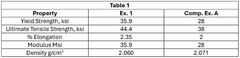
Figure IMGF000021_0001
Abstract
Description
Method for Densifying ArticlesCROSS-REFERENCE TO RELATED APPLICATIONS
[0001] This application claims priority to U.S. Provisional Application No. 63 / 556,654 filed February 22, 2024. The content of which is incorporated herein by referenceTECHNICAL FIELD
[0002] The present disclosure relates to a method of densifying articles using a porous mold. In particular, the present disclosure relates to producing articles from metal powder via a porous mold and an enclosure and subjecting these to an isostatic pressing wherein the metal powder is not sintered.BACKGROUND
[0003] Additive manufacturing (AM) techniques have been employed to make molds that are used to densify articles. One such AM technique is binder jetting. In binder jetting, after the deposition of metal powder, a liquid binding agent is selectively deposited to bond powder particles together. The finished part is developed through the layering of powder and binder.
[0004] Binder jetting results in a green part. The green part is further processed by sintering in a furnace. Because binders are used in the binder jetting process and loose powder is removed duringthe process, molds made for binder jetting typically have pores in them. Conventionally, these types of porous molds are not used in densification processes such as hot isostatic pressing (HIP) because the porous molds are known to cause many problems duringthe HIP and densifying processes, e.g., open porosity and absence of a hermetic layer for HIP cans.
[0005] Porous molds may also have lower dimensional stability compared to non- porous molds. The material may expand or contract within the pores duringthe molding process, leading to variations in the final dimensions of the densified articles.
[0006] In some molding processes, releasing agents or mold release agents are used to facilitate the removal of the densified article from the mold. Porous molds may absorb these agents, affecting the release characteristics and potentially causing adhesion issues. To reduce or eliminate the pores in the molds, additional post processing steps such as curing, coating, or other finishing processes may be employed.
[0007] US Pat. Appl. No. 2016 / 0158843A1 describes a method of producing full density binder-jet printed metallic articles. A metallic 3-D printed article is produced using a binder-jet printing method and is positioned in a hot isostatic press (HIP) container surrounded by stabilization powder. A vacuum is introduced into the inside of the HIP container. A binder used to bond powder articles together in the printed article is removed by heatingthe HIP container to decompose the binder and removing decomposition products by applying a vacuum to the HIP container. The HIP container is sealed with a vacuum therein and compacted under heat and pressure to remove all porosity in the printed article. The printed article thereafter is removed from the HIP container and finished to a final form.
[0008] US Pat. Appl. No. 2023 / 0059163 describes additive manufacture techniques that enable the densification of green articles prior to further article processing. The method of forming an article comprises providing a powder composition and formingthe powder composition into a green article by one or more additive manufacturing techniques. The green article is contacted with a powder pressure transfer media. The green article and powder pressure transfer media are then subjected to cold isostatic pressing (CIP) or warm isostatic pressing (WIP) at a pressure less than minimum isostatic compaction pressure of the powder pressure transfer media to provide a densified green article. It is important to note that CIP and WIP are operated at much lower temperatures than HIP, therefore the physical performance requirement for HIP cans are different from CIP and WIP cans.
[0009] US Pat. Appl. No. 2020 / 0307018 describes a method of making a sintered article comprises providing a composite article comprising a porous exterior printed from a powder composition via one or more additive manufacturing techniques, the porousexterior defining an interior volume and providing a loose powder component in the interior volume. The porous exterior and loose powder component are simultaneously sintered to provide the sintered article comprising a sintered interior and sintered exterior.
[0010] Even in view of these references, a need exists for a densification of process that employs HIP conditions and provides for improvements in densification alongwith improvements in dimensioning, distortion, and / ortolerances.SUMMARY
[0011] The present disclosure relates to a method for densifying articles, the method comprises depositing metal powder into a porous mold; packingthe porous mold in a load transmitting powder within an enclosure; and subjectingthe porous mold and the enclosure to hot isostatic pressing to form a densified article, wherein the densified article has a density greater than 80% of theoretical density; and the metal powder is not sintered. The porous mold may be not completely sealed, e.g., not hermetically sealed. The porous mold may have a greater than 10% porosity and / or an average pore size of less than 20 pm. The pore size of the porous mold may be less than the size of the metal powder. The densified article can demonstrate distortion of less than 10% and / or an improved dimensioning / tolerancing of less than 15%. The HIP is conducted at a temperature greater than 350 °C, at a pressure ranging from 60 to 400 MPa. The method may further comprise depositing mold powder to form the porous mold or mold parts using an additive manufacturing process, e.g., a binder jetting process. The porous mold or mold parts may be debound and / or sintered. The method may further comprise etching the porous mold from the densified article in an acidic environment. The mold powder can comprise iron. The metal powder can comprise beryllium, e.g., greater than 45 wt% of beryllium, less than 1 wt% of cobalt, less than 1 wt% of nickel, based on the total weight of the metal powder. The metal powder may have an average diameter of less than 45 microns, and / or a bimodal distribution of the metal powder has a ratio of coarse metal powder to fine metal powder from 10:1 to 2:1 , e.g., from 8:1 to 4:1 , wherein the coarse metal has an averagediameter from 50 to 400 microns, and the fine metal powder has an average diameter from 25 to 40 microns.DETAILED DESCRIPTION
[0012] As noted above, molds made with additive manufacturing methods, such as binder jetting, are typically not dense and have pores in them. Porous molds are not traditionally used in densifying and / or HIP processes because these molds cause myriad problems during densifying and open porosity (not a hermetically sealed surface), e.g., material penetration, poor dimensional stability, and the use of additional releasing agent. And to reduce or eliminate the pores in the molds, post processing steps such as curing, coating, or other finishing processes are generally needed, which add to unwanted complexity and cost.
[0013] The inventors have found that avoiding sintering of the metal powder provides benefits such as better definition of complex shapes, better material homogeneity in the molded products, and reduction or elimination of phase separation of different powder material components in the densified article. These benefits are not achieved in conventional systems where the metal powder are sintered, e.g., simultaneously sintered with the porous mold.
[0014] Some existing methods include forming a porous mold first via sintering, fill the porous mold with metal powder, then sinter the metal powder and the mold in a simultaneous sintering step. Sintering, while effective for bonding metal powders, has its limitations. One significant drawback is the retention of porosity within the material. Even though sintering increases the strength and structural integrity of the material, the process does not completely eliminate the voids between particles. This residual porosity can lead to reduced mechanical properties, such as lower tensile strength and fatigue resistance. Additionally, the presence of pores can make the material more susceptible to corrosion and wear, which can be detrimental in applications requiring high durability and reliability. The sintering process also requires precise control of temperature and atmosphere to achieve consistent results, which can be challenging and costly. These limitations makesintering less suitable for applications where fully dense and high-performance materials are required.
[0015] Using HIP to densify metal powders that is packed inside a porous mold, on the other hand, can overcome these deficiencies. HIP offers significant advantages over sintering, particularly in achieving fully dense materials. By applying both high temperature and high pressure in an inert gas environment, HIP process effectively eliminates porosity, resulting in materials with superior mechanical properties. The absence of voids enhances the material's tensile strength, fatigue resistance, and overall durability, making it ideal for critical applications in aerospace, medical implants, and high-performance engineering components. Additionally, the uniform pressure applied during HIP ensures isotropic properties, meaning the material exhibits consistent strength and performance in all directions. This process also allows for the consolidation of complex shapes and the healing of internal defects, further improvingthe quality and reliability of the final product. Overall, HIP provides a more robust and reliable solution for producing high-performance metal components compared to traditional sintering.
[0016] Further, it is believed that non-simultaneous sintering, unlike simultaneous sintering, provides for the ability to independently optimize the sintering conditions for each of the porous mold and the loose metal powder. By separating the sintering process for each, more uniform density and enhanced mechanical properties in the final product are achieved. Further, this approach beneficially minimizes the risk of defects and inconsistencies that often arise from simultaneous sintering, where the differingthermal and physical properties of the materials can lead to uneven sintering and compromised structural integrity. The non-simultaneous sintering allows for greater control over the manufacturing process, resulting in higher quality and more reliable components.
[0017] In some cases, the porous mold is not completely sealed, e.g., not hermetically sealed and / or has specific pore size and / or porosity, and these characteristics contribute to the aforementioned benefits. In contrast, known processes employ conventional molds (different or no porosity / pore size and / or complete sealing), which can result in failurescaused by weld cracking, and can also fail to spill out powder contents. As such, these known processes fail to demonstrate the aforementioned improvements and benefits.
[0018] Additionally, it is believed that the porous mold comprises pores having an average pore size that is smaller than the metal powder deposited within, which limits or prevents the metal powder from penetrating through the pores, while at the same time allowing air and moisture to pass through, thus contributingto the improved densification. The porous mold also provides strong enough dimensional stability without the porous mold being significantly deformed during the densifying process. When packing the porous mold in a load transmitting powder within an enclosure, the amount of load transferred to the porous mold is strong enough to densify articles without destroying the dimensional stability of the mold.
[0019] In addition, by using the porous mold within an enclosure to densify articles, the aforementioned additional steps of post-possessing such as curing, coating, or other finishing processes can be advantageously eliminated. Such method can promote production efficiency and decrease overall costs at the same time.
[0020] In known processes, the 3-D printed article is buried within the stabilization powder, i.e., the load transmitting powder as a green article, and the green article is debounded inside the load transmitting powder within an HIP can. The difference being that the porous mold in the present application is debounded outside the load transmitting powder. And for US Pat. Appl. No. 2023 / 0059163, it is important to note that CIP and WIP are operated at much lower temperatures than HIP, therefore the physical performance requirement for HIP cans are different from CIP and WIP cans.
[0021] Thus, in some embodiments, this disclosure relates to a method for densifying articles. The method comprises the steps of depositing metal powder into a porous mold and packingthe porous mold in a load transmitting powder within an enclosure. The (packed) porous mold (and the enclosure surrounding it) may be subjected to HIP to form the densified article, which has an unexpectedly high density, e.g., a density greater than 80% of theoretical density (along with the other aforementioned processing and / orperformance benefits). Importantly, the metal powder is not sintered, which contributes to the aforementioned benefits.
[0022] As described herein, the terms “molded article” and “densified article” are used interchangeably.Porous Mold
[0023] In some embodiments, the method comprises the step of depositing metal powder into a porous mold. As noted above, the porous mold has particular characteristics that contribute to and / or provide for the benefits discussed above. In some cases, the porous mold may be a mold that has a significant number of pores (in some cases, some may be interconnected) or open spaces throughout its structure. These pores can allow air, liquids, or gases to pass through the mold. In some cases, the porous mold is not completely sealed, e.g., not hermetically sealed. In contrast, conventional processes require hermetic sealing because it has been traditionally believed that a sealed mold is required to maintain high pressure and to provide a controlled environment. Without a hermetic seal, the open porosity does not allow a complete HIP densification. The disclosed process does not require sealing, and the benefits can be for example uniform pressure distribution, improved gas permeability, reduced heat transfer variability, enhanced cooling capability, cost savings, and flexibility in design.
[0024] In some embodiments, the porous mold comprises an opening. The opening can receive metal powder to be deposited within the porous mold. In use, the opening can be closed with a plug, e.g., an insulation plug.
[0025] In some embodiments, the porous mold has a greater than 10% porosity, e.g., greater than 12%, greater than 15%, greater than 18%, greater than 20%, greater than 22%, greater than 25%, or greater than 28%. In terms of ranges, the porous mold may have a porosity from 10% to 90%, e.g., from 10% to 85%, from 10% to 75%, from 10% to 65%, from 10% to 55%, from 12% to 50%, from 15% to 50%, from 15% to 45%, from 18% to 45%, from 20% to 45%, from 20% to 40%, or from 20% to 35%. In terms of upper limit, the porosity may be less than 90%, e.g., less than 85%, less than 80%, less than 75%, lessthan 70%, less than 65%, less than 60%, less than 55%, less than 50%, less than 45%, less than 40%, or less than 35%. Porosity may be measure by available techniques such as mercury intrusion porosimetry, microscopy techniques, and gas deposition methods.
[0026] The porous mold may have an average pore size of less than 20 pm, e.g., less than 18 pm, less than 16 pm, less than 1 pm, less than 12 pm, less than 10 pm, less than 8 pm, less than 6pm, less than 5 pm, less than 4 pm, or less than 3 pm. In terms of ranges, the average pore size may be from 1 to 20 pm, e.g., from 2 to 20 pm, from 2 to 18 pm, from 3 to 18 pm, from 4 to 18 pm, from 4 to 15 pm, from 5 to 15 pm, from 6 to 15 pm, from 7 to 14 pm, from 7 to 12 pm, or from 7 to 10 pm. The average pore size can be measured by available techniques such as mercury intrusion porosimetry, microscopy techniques, gas deposition methods, and Archimedes density.
[0027] In some embodiments, the depositing is achieved via an additive manufacturing process. The additive manufacturing method build a three-dimensional article using a layer-by-layer approach. There are several additive manufacturing techniques available to form the porous mold, including material jetting, binding jetting, material extrusion, powder bed fusion, sheet lamination or directed energy deposition. For purposes of the present disclosure, the additive manufacturing process will be described in terms of binding jetting or laser power bed fusion, but it should be understood that other additive manufacturing techniques may be used.
[0028] For example, some additive manufacturing process may begin with constructing a model of the article. This is typically done using a computer-aided design (CAD) model. The CAD model is then sliced into layers. In the binder jetting process, the sliced layers detail the design parameters of the part to be formed including the open cavity.
[0029] The binder jetting apparatus spreads a layer of the mold powder in a build box. Any suitable technique to deposit the initial layer may be used, including spreading, coating, brushing, rolling, spraying, or dispensing. After each layer is deposited a jetted fluid, referred to as a binder, is selectively applied by a printing mechanism to the build surface according to the model. The build surface refers to the upper most surface in thebuild box at any particular time. After depositingthe binder, the build box is moved, and another layer of the powder is deposited. In most processes it is convenient to lower the build platten. The process repeats until a body is formed according to the model. Overall, the binder jetting process does not require elevated temperature and is a lowtemperature process (less than 100 °C), which prevents introducing stress to the porous mold.
[0030] In some embodiments, the method comprises debind and / or sinter the porous mold. This step happens before packingthe porous mold in a load transmitting powder within an enclosure. The debinding and / or sintering the porous mold to pyrolyze the polymer binder from the binder jetting process and densify the porous mold. Such process can yield porous mold with better performance and is more economically advantageous when compared to the method in which the debind and / or sinter step happens within a load transmitting powder.
[0031] In some embodiments, the method comprises employingthe depositing step and sintering mold parts to form the porous mold. When usingthis approach, porous mold parts can be manufactured separately and then joined at a later time through, e.g., sintering, to make a larger porous mold. Joining porous mold parts can be advantageous, especially if the mold size exceeds binder jetting build box dimensions.
[0032] The mold powder used to make the porous mold may vary widely and can be any powder that is suitable for binding jetting. Non-limiting examples include iron, niobium, alumina, titania, zirconia, beryllium, silicon carbide, or alloys thereof. Because the mold powder is made into a porous mold, which then has a metal powder deposited within the porous mold, the mold powder, and the porous mold, may, in some cases, have a melting temperature that is close to the melting temperature of the metal powder deposited within.
[0033] In some embodiments, the method comprises depositing loose metal powder into a porous mold. In some cases, the loose metal powder may have a particle size that is greater than the pore size of the porous mold, which can advantageously retain the metalpowder inside the porous mold during the manufacturing process and can reduce or eliminate the possibility of blocking the pores of the porous mold.
[0034] In some embodiments, the mold can be printed in sections when a mold larger than the build box print envelope is required. Each printed section is cured and depowdered. The printed sections are assembled together to make a larger mold and placed inside a sintering furnace for debinding and sintering. Sinter bonding occurs at elevated temperatures because surfaces of the same print materials are making contact. The sinter bonds are of equal strength to the sinter binds inside the additively manufactured part.HIP Process
[0035] In some embodiments, the method comprises packing the porous mold in a load transmitting powder within an enclosure and subjecting the porous mold and the enclosure to HIP to provide a densified article. In some cases, the porous mold may be at least partially surrounded , e.g., surrounded or fully surrounded, by the load transmitting powder such that the load transmitting powder is in direct contact with the porous mold. In some cases, the porous mold, the load transmitting powder, and the enclosure are degassed.
[0036] The load transmitting powder may have a particle size that is greaterthan the pore size of the porous mold. When the load transmitting powder has a particle size that is too small the load transmitting powder may become trapped within the pores of the porous mold. In one embodiment, the load transmitting powder may have an average particle size from 5 pm to 1000 pm, e.g., from 10 pm to 900 pm, from 10 pm to 850 pm, from 20 pm to 800 pm, from 20 pm to 750 pm, from 20 pm to 650 pm, from 20 pm to 550 pm, from 20 pm to 450 pm, from 20 pm to 350 pm, from 20 pm to 250 pm, from 25 pm to 500 pm, from 25 pm to 450 pm, from 25 pm to 400 pm, from 25 pm to 350 pm, from 30 pm to 750 pm, from 30 pm to 500 pm, from 30 pm to 450 pm, from 30 pm to 400 pm, from 30 pm to 300 pm, or from 30 pm to 250 pm. For purposes of the isostatic pressing, the load transmitting powder may have a spherical, cylindrical, or irregular morphology.
[0037] In some embodiments, the load transmitting powder is a ceramic powder. The ceramic powder may include alumina, silicon carbide, zirconia, titania, fused silica, or combinations thereof. In one embodiment, the load transmitting powder is alumina. The ceramic powder may be a loose powder. To prevent a failure in structural integrity, in some cases, the ceramic powder does not liquify during the isostatic pressing.
[0038] By usingthe isostatic pressing the embodiments may be able to achieve a densified article that has a reduced presence of internal defects, including voids. Under some conditions this may allow the residual porosity of the densified article to be significantly reduced or eliminated.
[0039] In some embodiments, HIP can densify complex shapes and allows for a higher degree of densification that uniaxial processes. In some cases, the enclosure is strong enough to maintain its integrity under the isostatic pressure without splitting, fracturing, or otherwise rupturing, but deforms to transfer the isostatic pressure to form the densified article.
[0040] The HIP may operate at temperatures greater than 350 °C, e.g., greater than 400 °C, greater than 450 °C, greater than 550 °C, greater than 600 °C, greater than 650 °C, greater than 750 °C, greater than 850 °C, greater than 950 °C, greater than 1000 °C, greater than 1100 °C, greater than 1200 °C, greater than 1300 °C, greater than 1400 °C, greater than 1500 °C, greater than 1600 °C, greater than 1700 °C, greater than 1800 °C, greater than 1900 °C, greater than 2000 °C, greater than 2100 °C, or greater than 2200 °C. In terms of ranges, the HIP may operate at temperatures from 350 to 2300 °C, e.g., from 400 to 2200 °C, from 500 to 2200 °C, from 550 to 2200 °C, from 600 to 2100 °C, from 600 to 2000 °C, from 600 to 1850 °C, from 600 to 1500 °C, from 600 to 1350 °C, from 600 to 1100 °C, from 600 to 950 °C, from 600 to 850 °C, from 600 to 750 °C, from 650 to 1850 °C, from 700 to 2200 °C, from 750 to 2100 °C, from 750 to 1850 °C, orfrom 800 to 1850 °C. In terms of upper limit, the HIP may operate at temperatures less than 2300 °C, e.g., less than 2250 °C, less than 2200 °C, less than 2100 °C, less than 2000 °C, less than 1900 °C, less than 1850 °C, less than 1800 °C, less than 1750 °C, less than 1700 °C, less than 1600 °C, lessthan 1500 °C, less than 1400 °C, less than 1300 °C, less than 1200 °C, less than 1100 °C, less than 1000 °C, less than 950 °C, less than 900 °C, less than 800 °C, less than 700 °C, less than 600 °C, less than 500 °C, less than 400 °C, or less than 350 °C.
[0041] In one embodiment, the HIP may operate at a pressure from 40 to 250 MPa, e.g., from 40 to 240 MPa, from 50 to 230 MPa, from 50 to 220 MPa, from 50 to 210 MPa, from 50 to 200 MPa, from 60 to 195 MPa, from 60 to 185 MPa, from 60 to 180 MPa, from 70 to 170 MPa, from 70 to 160 MPa, from 70 to 150 MPa, from 80 to 140 MPa, from 80 to 130 MPa, or from 80 to 120 MPa.
[0042] In one embodiment, the HIP may operate at a pressure from 40 to 550 MPa, e.g., from 40 to 540 MPa, from 50 to 530 MPa, from 50 to 520 MPa, from 50 to 510 MPa, from 50 to 500 MPa, from 60 to 480 MPa, from 60 to 450 MPa, from 60 to 430 MPa, or from 60 to 400 MPa.
[0043] In terms of lower limit, the HIP may operate at a pressure greater than 40 MPa, e.g., greater than 50 MPa, greater than 60 MPa, greater than 70 MPa, greater than 80 MPa, greater than 90 MPa, greater than 100 MPa, greater than 105MPa, greater than 110 MPa, greaterthan 120 MPa, greater than 130 MPa, greater than 140 MPa, greater than 150 MPa, greater than 160 MPa, greater than 170 MPa, greater than 180 MPa, greater than 190 MPa, greater than 200 MPa, greater than 210 MPa, greater than 220 MPa, greater than 230 MPa, or greater than 240 MPa. In terms of upper limit, the HIP may operate at a pressure less than 550 MPa, e.g., less than 530 MPa, less than 520 MPa, less than 510 MPa, less than 500 MPa, less than 490 MPa, less than 480 MPa, less than 470 MPa, less than 460 MPa, less than 450 MPa, less than 440 MPa, less than 430 MPa, less than 420 MPa, less than 410 MPa, less than 400 MPa, less than 390 MPa, less than 380 MPa, less than 370 MPa, less than 360 MPa, or less than 350 MPa,.
[0044] During the HIP process, the process may use a quenching technique such as uniform rapid coolingthat can provide cooling up to 100°C / min., e.g., up to 80°C / min. or up to 70°C / min. The cooling may involve circulating a gas to cool the densified article. For the hot isostatic process, the controlled cooling may restrict grain growth and thermaldistortion of the densified article. In addition, surface contamination may be reduced. In some embodiments, the method may include applying multiple cycles of isostatic pressing.
[0045] After the hot isostatic pressing, the densified article can be separated from the load transmitting powder. In one embodiment, the method comprises etching the mold from the densified article in an acidic environment. The acidic environment may be provided by an oxidizing acid, e.g., nitric acid, perchloric acid, sulfuric acid, chromic acid, and periodic acid.
[0046] Obtaining sufficient density from additively manufactured articles may result in articles with high quality and good mechanical properties. In one embodiment, the process produces densified articles after isostatic pressing that may be greater than 90% theoretical density, e.g., greater than 95% theoretical density, greater than 96% theoretical density, greater than 97% theoretical density, greater than 98% theoretical density, greater than 99% theoretical density, or greater than 99.5% theoretical density. In terms of ranges the densified articles may be from 90% to 100% theoretical density, e.g., from 90% to 99.9% theoretical density, from 92% to 99.9% theoretical density, from 95% to 99.9% theoretical density, from 95% to 99.5% theoretical density, from 92% to 99% theoretical density, or from 93% to 98.5% theoretical density.Metal Powder
[0047] The metal powder uses to make the densified article can be any suitable metal powder, e.g., metal powders that have a lower melting point than the porous mold.
[0048] In some embodiments, the metal powder comprises beryllium. The metal powder may comprise greater than 45 wt% of beryllium based on the total weight of the metal powder, e.g., greater than 45 wt%, greater than 48 wt%, greater than 50 wt%, greater than 55 wt%, greater than 58 wt%, greater than 60 wt%, greater than 65 wt%, greater than 68 wt%, greater than 70 wt%, greater than 75 wt%, greater than 78 wt%, greater than 80 wt%, greater than 85 wt%, greater than 90 wt%, greater than 95 wt%, greater than 97 wt%, greater than 98 wt%, greater than 99 wt%, or greater than 99.5 wt%. In terms of ranges themetal powder may comprise from 95 wt% to 100 wt% of beryllium based on the total weight of the metal powder, e.g., from 95 wt% to 99.9 wt%, from 96 wt% to 99.5 wt%, from 97 wt% to 99.5 wt%, from 98 wt% to 99.5 wt%, from 99 wt% to 99.5 wt%, or from 97 wt% to 99 wt%.
[0049] In some embodiments, the metal powder comprises from 45 to 75 wt% of beryllium based on the total weight of the metal powder, e.g., from 45 to 70 wt%, from 45 to 68 wt%, from 45 to 65 wt%, from 50 to 75 wt%, from 55 to 75 wt%, from 60 to 75 wt%, from 60 to 70 wt%, or from 60 to 65 wt%.
[0050] The metal powder may comprise other metals. In some cases, high purity beryllium is used. In one embodiment, the metal powder comprises less than 1 wt% of cobalt based on the total weight of the metal powder, e.g., less than 0.75 wt%, less than 0.5 wt%, less than 0.25 wt% or less than 0.1 wt%. In one embodiment, the metal powder comprises less than 1 wt% of nickel based on the total weight of the metal powder, e.g., less than 0.75 wt%, less than 0.5 wt%, less than 0.25 wt% or less than 0.1 wt%. Other metals that may be present that do not exceed the weight percentage of cobalt or nickel, respectively. The composition of the metal powder may behave homogenously when deposited in the build box to prevent segregation of particles that lead to inconsistent results.
[0051] In some embodiments, the metal powder comprises aluminum. The metal powder may comprise greater than 25 wt% of aluminum based on the total weight of the metal powder, e.g., greater than 25 wt%, greater than 30 wt%, greater than 35 wt%, greater than 40 wt%, greater than 45 wt%, greater than 50 wt%, greater than 55 wt%, greater than 60 wt%, greater than 65 wt%, greater than 70 wt%, greater than 75 wt%, greater than 80 wt%, greater than 85 wt%, greater than 90 wt%, greater than 95 wt%, greater than 97 wt%, greater than 98 wt%, or greater than 99 wt%. In terms of ranges the metal powder may comprise from 95 wt% to 100 wt% of aluminum based on the total weight of the metal powder, e.g., from 95 wt% to 99.9 wt%, from 96 wt% to 99.5 wt%, from 97 wt% to 99.5 wt%, from 98 wt% to 99.5 wt%, from 99 wt% to 99.5 wt%, or from 97 wt% to 99 wt%.
[0052] In some embodiments, the metal powder comprises from 25 to 55 wt% of aluminum based on the total weight of the metal powder, e.g., from 25 to 50 wt%, from 25 to 45 wt%, from 25 to 40 wt%, from 30 to 55 wt%, from 35 to 55 wt%, from 35 to 50 wt%, from 35 to 45 wt%, or from 35 to 40 wt%.
[0053] The metal powder may comprise other metals. In some cases, high purity aluminum is used. In one embodiment, the metal powder comprises less than 1 wt% of cobalt based on the total weight of the metal powder, e.g., less than 0.75 wt%, less than 0.5 wt%, less than 0.25 wt% or less than 0.1 wt%. In one embodiment, the metal powder comprises less than 1 wt% of nickel based on the total weight of the metal powder, e.g., less than 0.75 wt%, less than 0.5 wt%, less than 0.25 wt% or less than 0.1 wt%. Other metals that may be present that do not exceed the weight percentage of cobalt or nickel, respectively. The composition of the metal powder may behave homogenous when deposited in the build box to prevent segregation of particles that lead to inconsistent results.
[0054] The metal powder may have a morphology that is irregular, polygonal, spherical, or combination thereof. Morphology may be determined by SEM images. In one embodiment, greater than 50% of the metal powder have an aspect ratio of 2:1 to 1 :1 , e.g., greater than 60% of the metal powder have an aspect ratio of 2:1 to 1 :1 or greater than 75% of the metal powder have an aspect ratio of 2:1 to 1 :1 .
[0055] In some embodiments, the metal powder exhibits a Gaussian particle size distribution. The metal powder, which may comprise beryllium and / or aluminum, may have an average (d50) diameter of less than 45 microns, e.g., less than 40 microns, less than 35 microns, less than 30 microns, less than 25 microns, or less than 20 microns. In terms of ranges, the metal powder may have an average (d50) diameter from 1 to 45 microns, e.g., from 1 to 40 microns, from 5 to 40 microns, from 5 to 35 microns, from 5 to 30 microns, or from 10 to 25 microns. The size of the metal powder allows the metal powder to be deposited in adequate manner in the build box. Particle distributioncorresponding to 50% in the cumulative distribution curve is referred to as the average particle size.
[0056] In other embodiments, the metal powder may have a bimodal distribution. A bimodal distribution may have a ratio of coarse particles to fine particles. Coarse particles may have an average (d50) diameter of greater than 50 microns, e.g., greater than 55 microns, greater than 60 microns or greater than 75 microns. In terms of ranges the coarse particles may have average (d50) diameter from 50 to 400 microns, e.g., from 50 to 300 microns, or from 75 to 150 microns. Fine particles may have an average (d50) diameter of less than 40 microns, e.g., less than 30 microns, less than 25 microns or less than 10 microns. Fine particles may have an average (d50) diameter ranging from 0.01 to 40 microns, e.g., from 0.5 to 40 microns, from 1 to 40 microns, from 1 to 35 microns, from 5 to 35 microns, from 10 to 30 microns, from 15 to 30 microns, from 20 to 30 microns, from 15 to 40 microns, from 20 to 40 microns, from 25 to 40 microns, from 20 to 35 microns, from 30 to 40 microns, or from 30 to 35 microns. The fine particles may be on the nano scale and may be less than 1 microns in some embodiments. Accordingly, the nano scale fine particles may be from 1 nm to 950 nm, e.g., from 10 nm to 700 nm or from 50 nm to 550 nm. The ratio of coarse particles to fine particles in a bimodal distribution may be from 10:1 to 2:1 , e.g., from 8:1 to 3:1 , from 8:1 to 4:1 , or from 6:1 to 4:1 . The coarse and fine particles may have similar morphology, i.e. both spherical, and different morphologies including different aspect ratios.
[0057] In some embodiments, the metal powder has an apparent density that may be greater than 50% of the theoretical density of the metal powder, e.g., greater than 60%, greater than 70%, or greater than 80%. The apparent density may be assessed using the Carneyfunnel accordingto the ASTM Standard B417 (Standard Test Method for Apparent Density of Non-Free-Flowing Metal Powders Using the Carney Funnel).
[0058] In some embodiments, the metal powder has a tapped density. In one embodiment, the tapped density may be greater than 60% of the theoretical density of the metal powder, e.g., greater than 65%, greater than 70%, greater than 80%, greater than85%, greater than 90%, or greater than 95%. Tapped density may be measured using a graduated cylinder as described by ASTM Standard B527 (“Standard Test Method for Tapped Density of Metal Powders and Compound.”). The measurement may be obtained by mechanically tapping until little further volume change is observed. Tapped density may be calculated as the mass divided by the final volume of the metal powder.
[0059] In some embodiments, the densified article has a density greater than 80% of the theoretical density, e.g., greater than 80%, greater than 85%, greater than 90%, greater than 92%, greater than 95%, greater than 98%, greater than 99%, or greater than 99.5%. In terms of upper limits, the densified article may have a density less than 99.9%, e.g., less than 99.8%, less than 99.5%, less than 99%, less than 98.5%, less than 98%, less than 96%, less than 95%, less than 93%, less than 92%, less than 90%, less than 85%, or less than 80%. In terms of ranges, the densified article may have a density from 80% to 99.9%, e.g., from 80% to 99.9%, from 82% to 99.9%, from 83% to 99.9%, from 84% to 99.9%, from 85% to 99.9%, from 90% to 99.9%, from 92% to 99.9%, from 95% to 99.9%, from 98% to 99.9%, from 95% to 99.5%, from 95% to 99%, from 95% to 98%, or from 98% to 99%. Physical Performance
[0060] Distortion in molded articles can provide valuable information about the quality and performance of the manufacturing method. Generally speaking, a lower distortion percentage is desirable and indicates a better manufacturing method.
[0061] Distortion of molded articles can be measured using various methods such as visual inspection, coordinate measurement machines, 3D scanning, profile projection, digital image correlation, and comparative measurement. The distortion of the articles made through conventional binder jetting usually is greater than 10-15%.
[0062] In one embodiment, the densified article demonstrates a distortion of less than10%, e.g., less than 9%, less than 8%, less than 7%, less than 6%, less than 5%, less than4%, less than 3%, less than 2%, or less than 1 %. In terms of ranges, the densified article demonstrates a distortion from 1% to 10%, e.g., from 1% to 9%, from 2% to 9%, from 2% to8%, from 3% to 8%, from 3% to 7.5%, from 4% to 8%, from 4% to 7.5%, from 5% to 8%, or from 5% to 7.5%.
[0063] Dimensioning and tolerancing Likewise provide valuable information about the quality and performance of the manufacturing method. Generally speaking, a Lower dimensioning and tolerancing percentage is desirable and indicates a better manufacturing method. The dimensioning and tolerancing of the articles made through conventional binder jetting usually is greaterthan 10-15%.
[0064] In one embodiment, the densified article demonstrates improved dimensioning and / or tolerancing of less than 15%, e.g., less than 14%, less than 13%, less than 12%, less than 11%, less than 10%, less than 9%, less than 8%, less than 7%, less than 6%, or less than 5%. In terms of ranges, the densified article demonstrates improved dimensioning and / or tolerancing from 1% to 15%, e.g., from 2% to 15%, from 3% to 15%, from 3% to 10%, from 3% to 9%, from 5% to 10%, or from 5% to 8%.
[0065] In one embodiment, the densified article is machined to a mini-tensile shape. The mini-tensile is subject to various tension testing of metallic materials accordingto ASTM E-8 (2024).
[0066] In one embodiment, the mini-tensile demonstrates a yield strength of greater than 30 ksi, e.g., greater than 31 ksi, greater than 32 ksi, greater than 33 ksi, greater than 34 ksi, greater than 34.5 ksi, greater than 35 ksi, greater than 35.5 ksi, greater than 36 ksi, greater than 36.5 ksi, greater than 37 ksi, greater than 38 ksi, greater than 39 ksi, greater than 40 ksi, greater than 42 ksi, greater than 45 ksi, greater than 48 ksi, greater than 50 ksi, greater than 52 ksi, greater than 55 ksi, greater than 58 ksi, or greater than 60 ksi.
[0067] In one embodiment, the mini-tensile demonstrates an ultimate tensile strength of greater than 40 ksi, e.g., greater than 41 ksi, greater than 42 ksi, greater than 42.5 ksi, greater than 43 ksi, greater than 43.5 ksi, greater than 44 ksi, greater than 44.5 ksi, greater than 45 ksi, greater than 46 ksi, greater than 47 ksi, greater than 48 ksi, greater than 50 ksi, greater than 52 ksi, greater than 55 ksi, greater than 58 ksi, greater than 60 ksi, greater than65 ksi, greater than 70 ksi, or greater than 75 ksi.
[0068] In one embodiment, the mini-tensile demonstrates a modulus of greater than 30 Msi, e.g., greater than 31 Msi, greater than 32 Msi, greater than 33 Msi, greater than 33.5 Msi, greater than 34 Msi, greater than 34.5 Msi, greater than 35 Msi, greater than 35.5 Msi, greater than 36 Msi, greater than 37 Msi, greater than 38 Msi, greater than 39 Msi, greater than 40 Msi, greater than 42 Msi, greater than 45 Msi, greater than 48 Msi, greater than 50 Msi, greater than 52 Msi, greater than 55 Msi, greater than 58 Msi, greater than 60 Msi, or greater than 65 Msi.
[0069] In one embodiment, the mini-tensile demonstrates an elongation of greater than 2%, e.g., greater than 2.1 %, greater than 2.15%, greater than 2.2%, greater than 2.25%, greater than 2.3%, greater than 2.34%, greater than 2.4%, greater than 2.45%, greater than 2.5%, greater than 2.6%, greater than 2.8%, greater than 3%, greater than 3.2%, greater than 3.4%, greater than 3.6%, greater than 3.8%, greater than 4%, greater than 4.2%, greater than 4.5%, greater than 4.8%, greater than 5%, greater than 5.2%, greater than 5.5%, greater than 5.8%, or greater than 6%.Examples
[0070] The following examples are non-limiting.
[0071] An article (Ex. 1) was made using the method described herein. Specifically, a porous beryllium mold was made through a binder jetting process. During the binder jetting process, powder layers having 65 microns thickness and 50% binder saturation were printed using spherical beryllium powder (average diameter size of 25 microns) as the mold powder, and Clean Fuse™ binder from ExOne. The debinding of the mold powder layers occurred at 470 °C in a hydrogen atmosphere, and sintered at 1250 - 1270 °C in an argon atmosphere, to form a porous mold. Next, an aluminum / beryllium powder comprising 35-40 wt% of aluminum and 60-65 wt% of beryllium, having an average diameter of 23 microns was packed into the porous mold and tapped, with a tapped density of 1 .4-1.45 g / cm3. The packed porous mold was then transferred into an enclosure (an HIP can) containing load transmitting powder (alumina powder). The packed enclosure (HIP can with the packed porous mold) was then subjected to a HIP process at 610 °C and104 MPa. The metal powder was not sintered in the preparation of Ex. 1 , nor were the metal powder and the porous mold sintered together.
[0072] After the HIP process was completed, the porous mold was removed from the HIP can, and the molded densified article was removed from the porous mold. The molded densified article was machined to a mini-tensile having a dimension of around 0.52” end diameter, 0.25” gauge diameter, 1 .260” gauge length, and 2.5” overall length.
[0073] The molded densified article was tested for yield strength, the ultimate tensile strength, modulus, and elongation, according to ASTM E-8 (2024). The density of the molded densified article was measured according to ASTM B311 -22 (2022).
[0074] A comparative example (Comp. Ex. A) was prepared by cutting a mini-tensile directly off from a piece of aluminum / beryllium metal. The aluminum / beryllium metal piece was prepared by directly HIP-ing an aluminum / beryllium powder mixture inside an enclosure (HIP container) at 610 °C and 104 MPa, without the use of any porous mold. The performance data comparisons between Ex. 1 and Comp. Ex. A are as follows in Table 1 . Comp. Ex. A does not employ a porous mold and, as such, the metal powder and the porous mold were also not sintered together.
[0075] As is shown in Table 1 , the molded article Ex. 1 made from the claimed process outperforms Comp. Ex. A in all mechanical tests. For example, the yield strength has a 28.2% increase, the ultimate tensile strength has a 17.1 % increase, the elongation has a 17.5% increase, the modulus has a 28.2% increase, while maintaining a similar density than that of the Comp. Ex. A. These enhancements highlight the effectiveness of the claimed process in producing a molded article with better overall mechanical characteristics.
[0076] The present disclosure has been described with reference to exemplary embodiments. Obviously, modifications and alterations will occur to others upon reading and understandin the preceding detailed description. It is intended the present disclosure be construed as including all such modifications and alterations as far as they come within the scope of the appended claims or the equivalents thereof. In some embodiments, any or some of the steps or components disclosed herein may be considered optional. In some cases, any or some of the aforementioned items in this description may be expressly excluded, e.g., via claim language. For example, claim language may be modified to recite additional process steps.
[0077] While the invention has been described in detail, modifications within the spirit and scope of the invention will be readily apparent to those of skill in the art. In view of the foregoing discussion, relevant knowledge in the art and references discussed above in connection with the Background and Detailed Description, the disclosures of which are all incorporated herein by reference. In addition, it should be understood that aspects of the invention and portions of various embodiments and various features recited below and / or in the appended claims may be combined or interchanged either in whole or in part. In the foregoing descriptions of the various embodiments, those embodiments which refer to another embodiment may be appropriately combined with other embodiments as will be appreciated by one of skill in the art. Furthermore, those of ordinary skill in the art will appreciate the foregoing description is by way of example only and is not intended to limit.
[0078] As used herein, “greater than” and “less than” limits may also include the number associated therewith. Stated another way, “greater than” and “less than” may be interpreted as “greater than or equal to” and “less than or equal to.” It is contemplated that this language may be subsequently modified in the claims to include “or equal to.” For example, “greater than 4.0” may be interpreted as, and subsequently modified in the claims as “greater than or equal to 4.0.”
[0079] Some of the components and steps disclosed herein may be considered optional. In some cases, the disclosed compositions, processes, etc. may expresslyexclude one or more of the aforementioned components or steps in this description, e.g., via claim language. This is contemplated herein by the inventors. For example, claim language may be modified to recite that the disclosed compositions, processes, streams, etc., do not utilize or comprise one or more of the aforementioned components or steps, e.g., the metal powder does not comprise chromium. Such negative limitations are contemplated, and this text serves as support for negative limitations for components, steps, and / or features.
[0080] Unless otherwise defined, all technical and scientific terms used herein have the same meaning as commonly understood by one of ordinary skill in the art. In case of conflict, the present document, including definitions, will control. Some methods and materials are described below, although methods and materials similar or equivalent to those described herein can be used in practice or testing of the present disclosure. All publications, patent applications, patents and other references mentioned herein are incorporated by reference in their entirety. The materials, methods, and examples disclosed herein are illustrative only and not intended to be limiting.
[0081] The singular forms “a,” “an,” and “the” include plural referents unless the context clearly dictates otherwise.
[0082] As used in the specification and in the claims, the term “comprising” may include the embodiments “consisting of” and “consisting essentially of.” The terms “comprise(s),” “include(s),” “having,” “has,” “can,” “contain(s),” and variants thereof, as used herein, are intended to be open-ended transitional phrases that require the presence of the named ingredients / steps and permit the presence of other ingredients / steps. However, such description should be construed as also describing compositions or methods as “consisting of” and “consisting essentially of” the enumerated ingredients / steps, which allows the presence of only the named ingredients / steps, along with any impurities that might result therefrom, and excludes other ingredients / steps.
[0083] Numerical values in the specification and claims of this application, as they relate to polymers or polymer compositions, reflect average values for a composition thatmay contain individual polymers of different characteristics. The numerical values disclosed herein should be understood to include numerical values which are the same when reduced to the same number of significant FIGURES and numerical values which differ from the stated value by less than the experimental error of conventional measurement technique of the type described in the present application to determine the value.
[0084] All ranges disclosed herein are inclusive of the recited endpoint and independently combinable (for example, the range of “from 1 micron to 40 microns” is inclusive of the endpoints, 1 micron and 40 microns, and all the intermediate values). The endpoints of the ranges and any values disclosed herein are not limited to the precise range or value; they are sufficiently imprecise to include values approximating these ranges and / or values.
[0085] As used herein, approximating language may be applied to modify any quantitative representation that may vary without resulting in a change in the basic function to which it is related. Accordingly, a value modified by a term or terms, such as “about” and “substantially,” may not be limited to the precise value specified, in some cases. The modifier “about” should also be considered as disclosingthe range defined by the absolute values of the two endpoints. For example, the expression “from about 2 to about 4” also discloses the range “from 2 to 4”. The term “about” may refer to plus or minus 10% of the indicated number. For example, “about 10%” may indicate a range of 9% to 11%, and “about 1 ” may mean from 0.9-1 .1 .
[0086] For the recitation of numeric ranges herein, each intervening number there between with the same degree of precision is explicitly contemplated. For example, for the range of 6-9, the numbers 7 and 8 are contemplated in addition to 6 and 9, and for the range 6.0-7.0, the number 6.0, 6.1 , 6.2, 6.3, 6.4, 6.5, 6.6, 6.7, 6.8, 6.9, and 7.0 are explicitly contemplated.Embodiments
[0087] Embodiment 1 : A method for densifying articles, the method comprising: depositing metal powder into a porous mold; packingthe porous mold in a load transmitting powder within an enclosure; and subjectingthe porous mold and the enclosure to hot isostatic pressing to form a densified article, wherein the densified article has a density greater than 80% of theoretical density, and wherein the metal powder is not sintered, e.g., wherein the porous mold and the metal powder are not simultaneously sintered, e.g., not sintered together.
[0088] Embodiment 2: The method of claim 1 , wherein the porous mold is not completely sealed, e.g., not hermetically sealed.
[0089] Embodiment 3: The method of any of Embodiments 1-2, wherein the porous mold has a greater than 10% porosity.
[0090] Embodiment 4: The method of any of Embodiments 1-3, wherein the porous mold has an average pore size of less than 20 pm.
[0091] Embodiment 5: The method of any of Embodiments 1-4, wherein the porous mold has a pore size, and the metal powder has a pore size greater than the porous mold pore size.
[0092] Embodiment 6: The method of any of Embodiments 1 -5, wherein the densified article demonstrates a distortion of less than 10%.
[0093] Embodiment 7: The method of any of Embodiments 1 -6, wherein the method demonstrates improved dimensioning and / or tolerancing of less than 15%.
[0094] Embodiment 8: The method of any of Embodiments 1 -7, wherein the hot isostatic pressing is conducted at a temperature greater than 350 °C.
[0095] Embodiment 9: The method of any of Embodiments 1 -8, wherein the hot isostatic pressing is conducted at a pressure ranging from 60 MPa to 400 MPa.
[0096] Embodiment 10: The method of any of Embodiments 1 -9, further comprising depositing mold powder to form the porous mold using an additive manufacturing process.
[0097] Embodiment 11 : The method of Embodiment 10, wherein the additive manufacturing process comprises binder jetting.
[0098] Embodiment 12: The method of any of Embodiments 1 -11 , further comprising depositing mold powder to form porous mold parts using an additive manufacturing process and sintering mold parts to form the porous mold.
[0099] Embodiment 13: The method of any of Embodiments 12, wherein the additive manufacturing process comprises binder jetting.
[0100] Embodiment 14: The method of any of Embodiments 1 -13, further comprising etchingthe mold from the densified article in an acidic environment.
[0101] Embodiment 15: The method of any of Embodiments 1 -14, wherein the metal powder comprises beryllium.
[0102] Embodiment 16: The method of any of Embodiments 1 -15, wherein the metal powder comprises greater than 45 wt% of beryllium based on the total weight of the metal powder.
[0103] Embodiment 17: The method of any of Embodiments 1 -16, wherein the metal powder comprises less than 1 wt% of cobalt based on the total weight of the metal powder.
[0104] Embodiment 18: The method of any of Embodiments 1 -17, wherein the metal powder comprises less than 1 wt% of nickel based on the total weight of the metal powder.
[0105] Embodiment 19: The method of any of Embodiments 1 -18, wherein the metal powder has an average diameter of less than 45 microns.
[0106] Embodiment 20: The method of any of Embodiments 1 -19, wherein the bimodal distribution of the metal powder has a ratio of coarse metal powder to fine metal powder from 10:1 to 2:1 , e.g., from 8:1 to 4:1 , wherein the coarse metal has an average diameter from 50 to 400 microns, and the fine metal powder has an average diameter from 25 to 40 microns.
[0107] Embodiment 21 : The method of any of Embodiments 1 -20, further comprising debinding and / or sinteringthe porous mold.
[0108] Embodiment 22: The method of any of Embodiments 1 -21 , wherein the porous mold and the metal powder are not simultaneously sintered.
[0109] Embodiment 23: The method of any of Embodiments 1 -22, wherein the porous mold is made from a mold powder comprising iron.
Claims
We Claim:1 . A method for densifying articles, the method comprising: depositing metal powder into a porous mold; packing the porous mold in a load transmitting powder within an enclosure; and subjecting the porous mold and the enclosure to hot isostatic pressing to form a densified article, wherein the densified article has a density greater than 80% of theoretical density, and wherein the metal powder is not sintered.
2. The method of claim 1 , wherein the porous mold is not hermetically sealed.
3. The method of claim 1 , wherein the porous mold has a greater than 10% porosity and / or an average pore size of less than 20 pm.
4. The method of claim 1 , wherein the porous mold has a pore size, and the metal powder has a pore size greater than the porous mold pore size.
5. The method of claim 1 , wherein the densified article demonstrates a distortion of less than 10%.
6. The method of claim 1 , wherein the method demonstrates improved dimensioning and / or tolerancing of less than 15%.
7. The method of claim 1 , wherein the hot isostatic pressing is conducted at a temperature greater than 350 °C and / or a pressure ranging from 60 MPa to 400 MPa.
8. The method of claim 1 , further comprising depositing mold powder to form the porous mold using an additive manufacturing process comprising binder jetting.
9. The method of claim 1 , further comprising depositing mold powder to form porous mold parts using an additive manufacturing process and sintering mold parts to form the porous mold.
10. The method of claim 1, further comprising etching the mold from the densified article in an acidic environment.
11. The method of claim 9, wherein the mold powder comprises iron.
12. The method of claim 1 , wherein the metal powder comprises greater than 45 wt% of beryllium based on the total weight of the metal powder.
13. The method of claim 1 , wherein the metal powder comprises less than 1 wt% of cobalt and / or less than 1 wt% of nickel based on the total weight of the metal powder.1 . The method of claim 1 , wherein the metal powder has an average diameter of less than 45 microns.
15. The method of claim 1 , wherein the bimodal distribution of the metal powder has a ratio of coarse metal powder to fine metal powder from 10:1 to 2:1 , e.g., from 8:1 to 4:1 , wherein the coarse metal has an average diameter from 50 to 400 microns, and the fine metal powder has an average diameter from 25 to 40 microns.
Citation Information
Patent Citations
Method of achieving full density binder jet printed metallic articles
US20160158843A1
Additive manufacturing techniques and applications thereof
US20200307018A1
Additive manufacturing of articles comprising beryllium
KR102440771B1
Additive manufacturing techniques and applications thereof
US20230059163A1
Process for the production of a component by producing a molding using a metal or ceramic powder as the starting material
US5217664A