Cylindrical-turnplate permanent magnet speed controller

A technology of permanent magnet governor and turntable, applied in the direction of asynchronous induction clutch/brake, etc., can solve the problems of large axial force, small area, small torque, etc., achieve simple installation and debugging, increase coupling area, and avoid axial The effect of thrust

Active Publication Date: 2010-09-22
QINGDAO SPRING ENERGY TECH
View PDF4 Cites 19 Cited by
  • Summary
  • Abstract
  • Description
  • Claims
  • Application Information

AI Technical Summary

Problems solved by technology

[0003] In this case, the permanent magnet speed governor is a new type of ideal choice in the field of motor speed regulation; but the coupling surface of the ordinary flat plate type permanent magnet speed governor is flat, the area is small, the torque is small, and the axial The force is large, the requirements on the bearing are high, and it is easy to be damaged

Method used


Image

  • Cylindrical-turnplate permanent magnet speed controller
  • Cylindrical-turnplate permanent magnet speed controller
  • Cylindrical-turnplate permanent magnet speed controller

Examples


Embodiment Construction

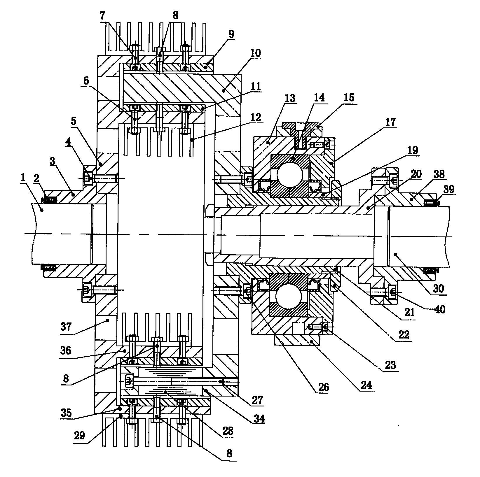
[0026] Referring now to the accompanying drawings of the description, the cylindrical turntable permanent magnet governor of the present invention will be further described in conjunction with specific embodiments.

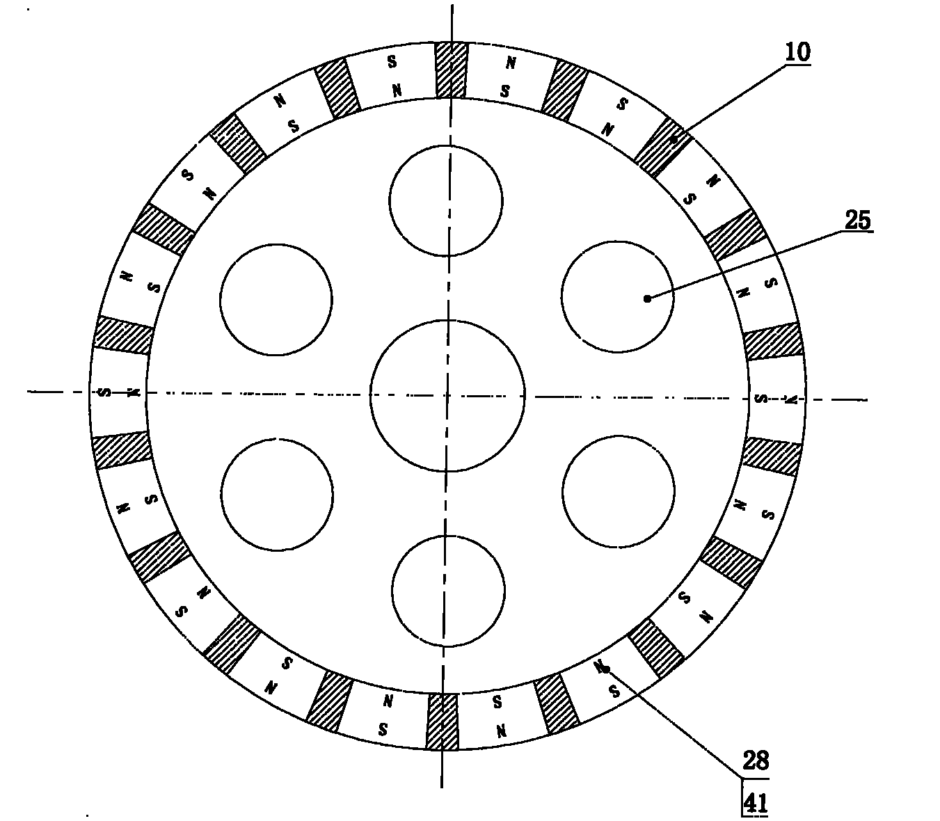
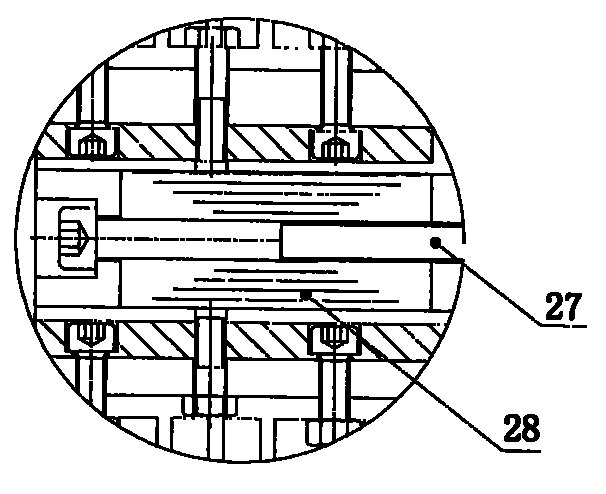
[0027] Working principle: The N and S poles of the magnets on the permanent disk are arranged adjacent to each other, and the magnetic field lines pass through the corresponding conductor cylinders. When the two move relative to each other, the conductor cylinders cut the magnetic force lines and generate eddy currents in the conductor cylinders. Eddy currents In turn, an anti-magnetic field is generated to prevent the relative movement between the two, so as to realize the torque transmission between the two. The greater the strength of the magnetic field passing between the two, the greater the transmitted torque; the faster the relative movement, the greater the transmitted torque; when the permanent magnet turntable is pushed and pulled by the bearing to move i...


PUM


Abstract

The invention relates to a cylindrical-turnplate permanent magnet speed controller, which comprises a first shaft and a second shaft; the first shaft is provided with a common-bottom double-cylinder steel turnplate, and an inner conductor cylinder and an outer conductor cylinder which are opposite to each other are arranged in an inner cylinder and an outer cylinder; the second shaft is provided with an additional shaft, a bushing and a permanent magnet turnplate, the bushing is connected with the additional shaft through splines, the permanent magnet turnplate is a single cylinder, and is made of nonferromagnetic material, the cylinder is provided with a circle of permanent magnets, the polar directions of which are perpendicular to the axial line of the turnplate, neighboring magnets are heterospolarly mounted, and the cylinder is arranged between the inner and the outer conductor cylinders; and an adjusting mechanism which comprises an inner round sleeve and an outer round sleeve is arranged outside the additional shaft and the bushing. Since the speed controller adopts cylindrical coupling to replace planar coupling, axial force does not exist, the coupled surface is large, moreover, the permanent magnet turnplate can axially move, the effective engaged parts of the permanent magnet turnplate and the conductor cylinders are changed, so that the torque transferred between the permanent magnet turnplate and the conductor cylinders can be changed, consequently, repeatable, regulatable and controllable output torque and rotation speed can be obtained, and energy can be saved in the process of speed regulation.

Description

technical field [0001] The invention relates to a driving speed regulating device, in particular to a cylindrical turntable permanent magnet speed regulating device adopting the principle of permanent magnet eddy current induction. Background technique [0002] Existing motor systems, especially centrifugal equipment systems, mainly use the following methods to regulate flow and pressure: damper baffles, valves, hydraulic couplings, frequency converters, and internal feedback chopper speed regulation. Dampers and valves are traditional methods, which can effectively adjust the flow or pressure, but the disadvantages are also obvious: they are not energy-saving, and they are easy to cause shocks in the system. Although the hydraulic coupling can adjust the speed and save energy to a certain extent, its efficiency is low and it is not stable enough. Inverter and internal feedback chopper speed regulation use the method of directly changing the motor speed to adjust the system...

Claims


Application Information

Patent Timeline
Patent Type & Authority Applications(China)
IPC IPC(8): H02K49/04
Inventor 王荣松
Owner QINGDAO SPRING ENERGY TECH
Why Eureka
Try Eureka