
Projection light source and projection system thereof
A light source and projection technology, applied in the field of projection display, can solve the problems of reducing the efficiency of the red light segment of the projection system, unable to take into account the color gamut and brightness, and low color gamut of the projection light source, so as to improve color purity, ensure brightness and color gamut, Improve the effect of color gamut
Patent Information
- Authority / Receiving Office
- CN · China
- Current Assignee / Owner
- Publication Date
- 2018-10-16
- Estimated Expiration
- Not applicable · inactive patent
Smart Images
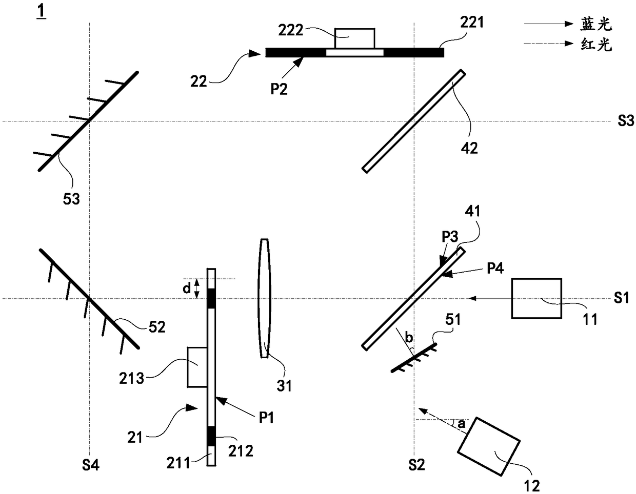
Figure 1 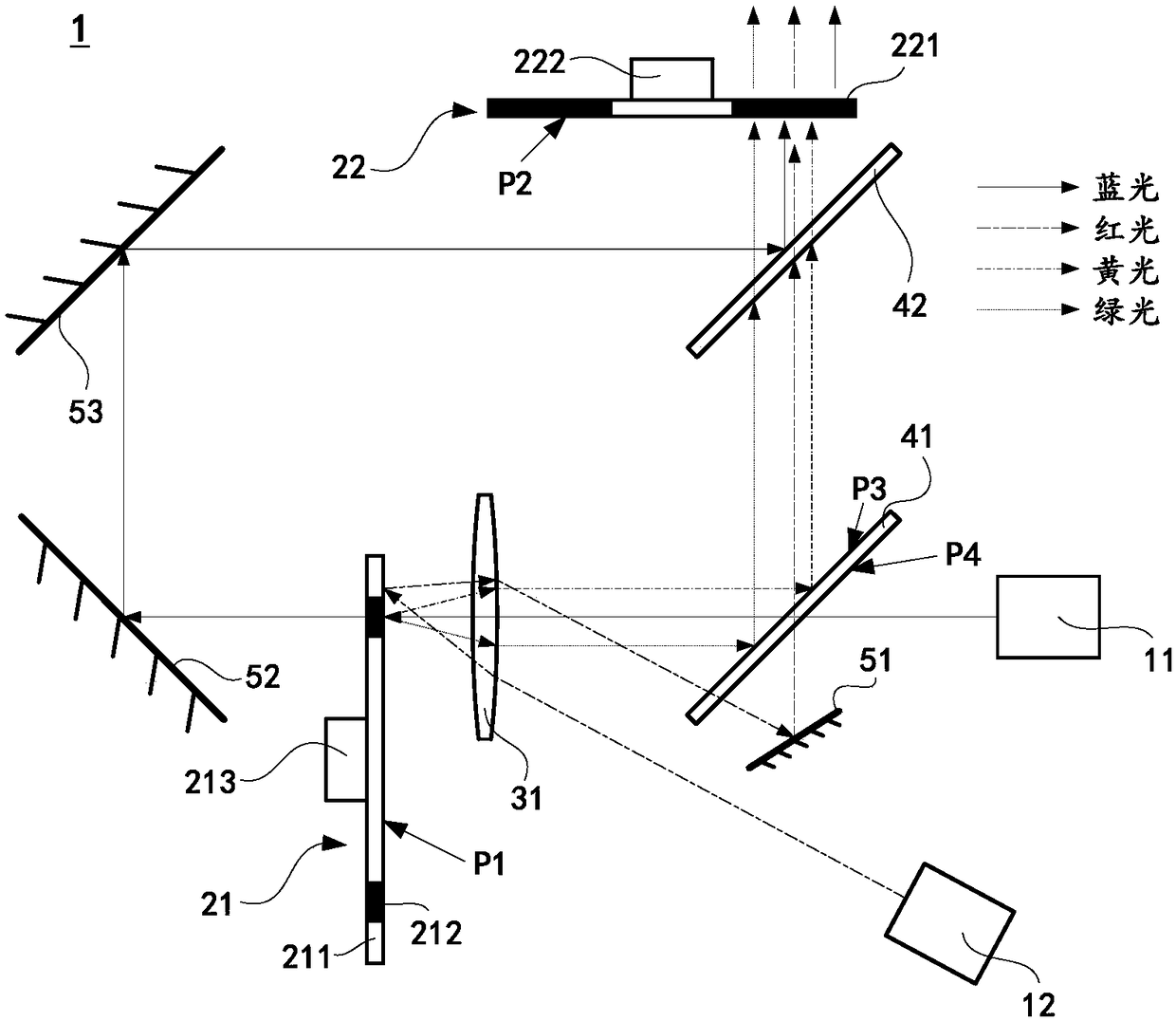
Figure 2 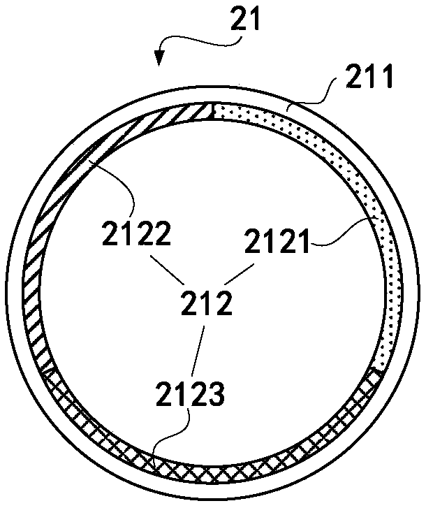
Figure 3
Abstract
Description
technical field
[0001] The embodiments of the present invention relate to the technical field of projection display, in particular to a projection light source and a projection system thereof. Background technique
[0002] Laser is a high-brightness, highly directional light source capable of emitting monochromatic coherent beams. In recent years, due to the many advantages of lasers, lasers have been gradually used as projection light sources in the field of projection display technology. Projection systems using lasers as projection light sources have long service life, rich colors and high screen brightness.
[0003] In the prior art, the projection light source of the projection system mostly adopts the blue laser to excite the phosphor, in which the blue light is directly provided by the blue laser, and the green light is generated by the blue laser to excite the green phosphor through the green filter section Filtered out, the red light is filtered out by the red filt...
Examples
Embodiment 1
[0057] see figure 1 , is a structural schematic diagram of a projection light source provided in an embodiment of the present invention. The projection light source 1 is applied to a projection system and includes: a blue laser light source 11, a red laser light source 12, a rotating fluorescent color wheel 21, and a rotating filter color wheel 22 , condenser lens 31, first beam splitter 41, second beam splitter 42, red laser reflector 51, first reflector 52 and second reflector 53, and, described blue laser light source 11, red laser light source 12 , rotating fluorescent color wheel 21, rotating filter color wheel 22, condenser lens 31, first beam splitter 41, second beam splitter 42, red laser reflector 51, first reflector 52 and second reflector 53 are all set on the same level.
[0058] Specifically, the blue laser light source 11 is used to emit blue laser beams, including a plurality of blue laser light-emitting chips (not shown), a first light combining device (not sh...
Embodiment 2
[0102] see Figure 4 , is a schematic structural diagram of a projection light source provided in an embodiment of the present invention. The projection light source 1 is applied to a projection system. The projection light source 1 is basically the same as the projection light source described in Embodiment 1. For the same content, refer to Embodiment 1, and then This will not repeat them one by one.
[0103] The distinguishing feature is that the projection light source 1 described in the embodiment of the present invention includes: a blue laser light source 11, a red laser light source 12, a rotating fluorescent color wheel 21, a rotating filter color wheel 22, a condenser lens 31, a first beam splitter Mirror 41, red laser reflector 51 and blue laser reflector 54.
[0104] Specifically, see Figure 6 , the annular fluorescent layer 212 of the rotating fluorescent color wheel 21 includes a green phosphor area 2121, a yellow phosphor area 2122 and a blue laser reflection ...
Embodiment 3
[0127] see Figure 7 , is a schematic structural diagram of a projection light source provided in an embodiment of the present invention. The projection light source 1 is applied to a projection system. The projection light source 1 is basically the same as the projection light source described in Embodiment 1. For the same content, refer to Embodiment 1, and then This will not repeat them one by one.
[0128] The distinguishing feature is that the projection light source 1 described in the embodiment of the present invention includes: a blue laser light source 11, a red laser light source 12, a rotating fluorescent color wheel 21, a rotating filter color wheel 22, a condenser lens 31, a first beam splitter mirror 41 and red laser mirror 51.
[0129] Specifically, see Figure 9 , the annular fluorescent layer 212 of the rotating fluorescent color wheel 21 includes a green phosphor area 2121, a yellow phosphor area 2122 and a blue laser reflection scattering area 2125, and th...