
Heart valve annulus device and method of using same
a heart valve and annulus technology, applied in the field of prosthetic heart valve anchors, can solve the problems of heart valve damage, needing complete valve replacement, and requiring complete valve replacement, so as to reduce the overall time needed, improve the maneuverability, and minimize the time-consuming process of suturing
Patent Information
- Authority / Receiving Office
- US · United States
- Patent Type
- Applications(United States)
- Current Assignee / Owner
- Publication Date
- 2005-09-29
- Estimated Expiration
- Not applicable · inactive patent
Smart Images
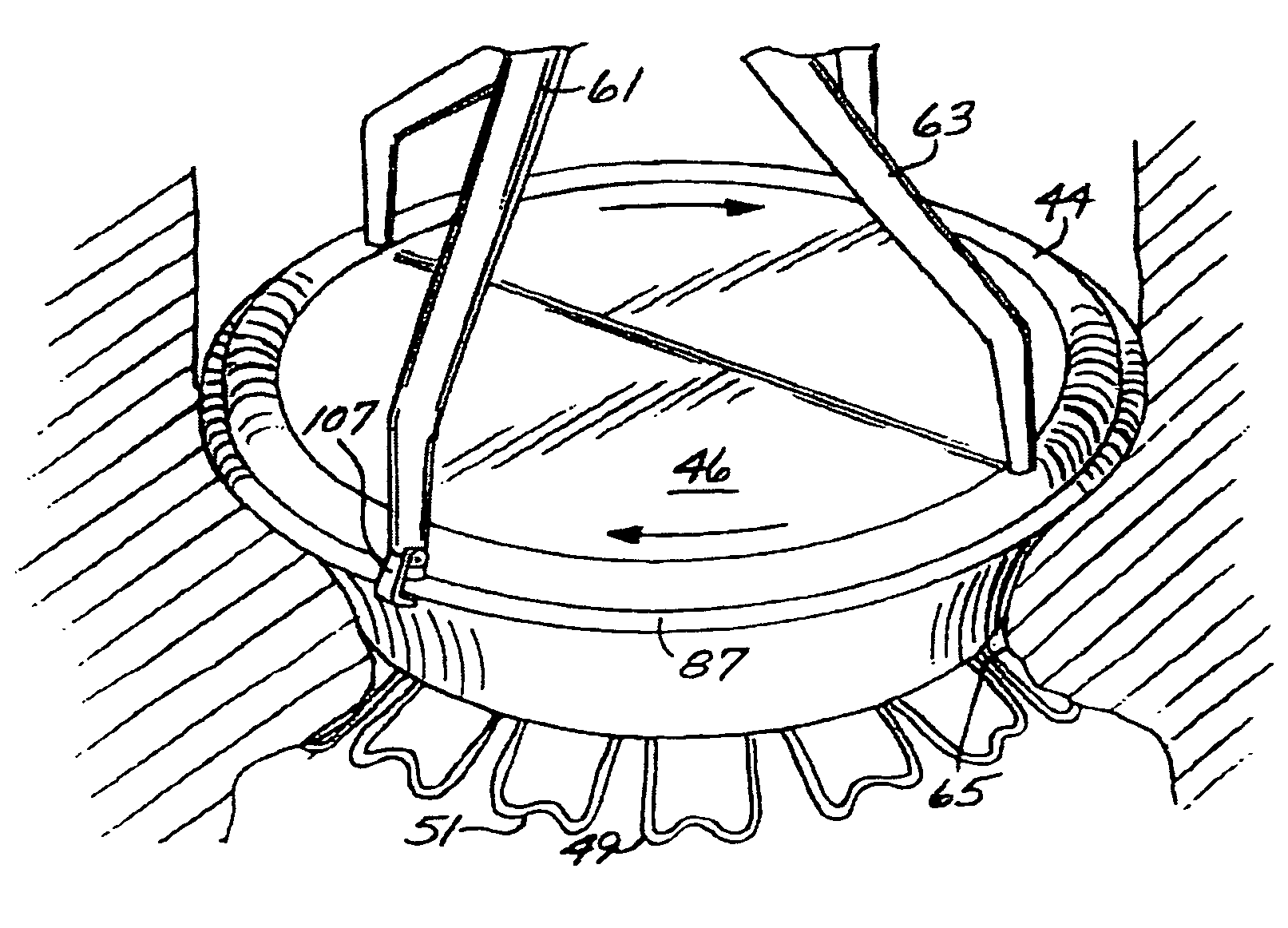
Figure 1 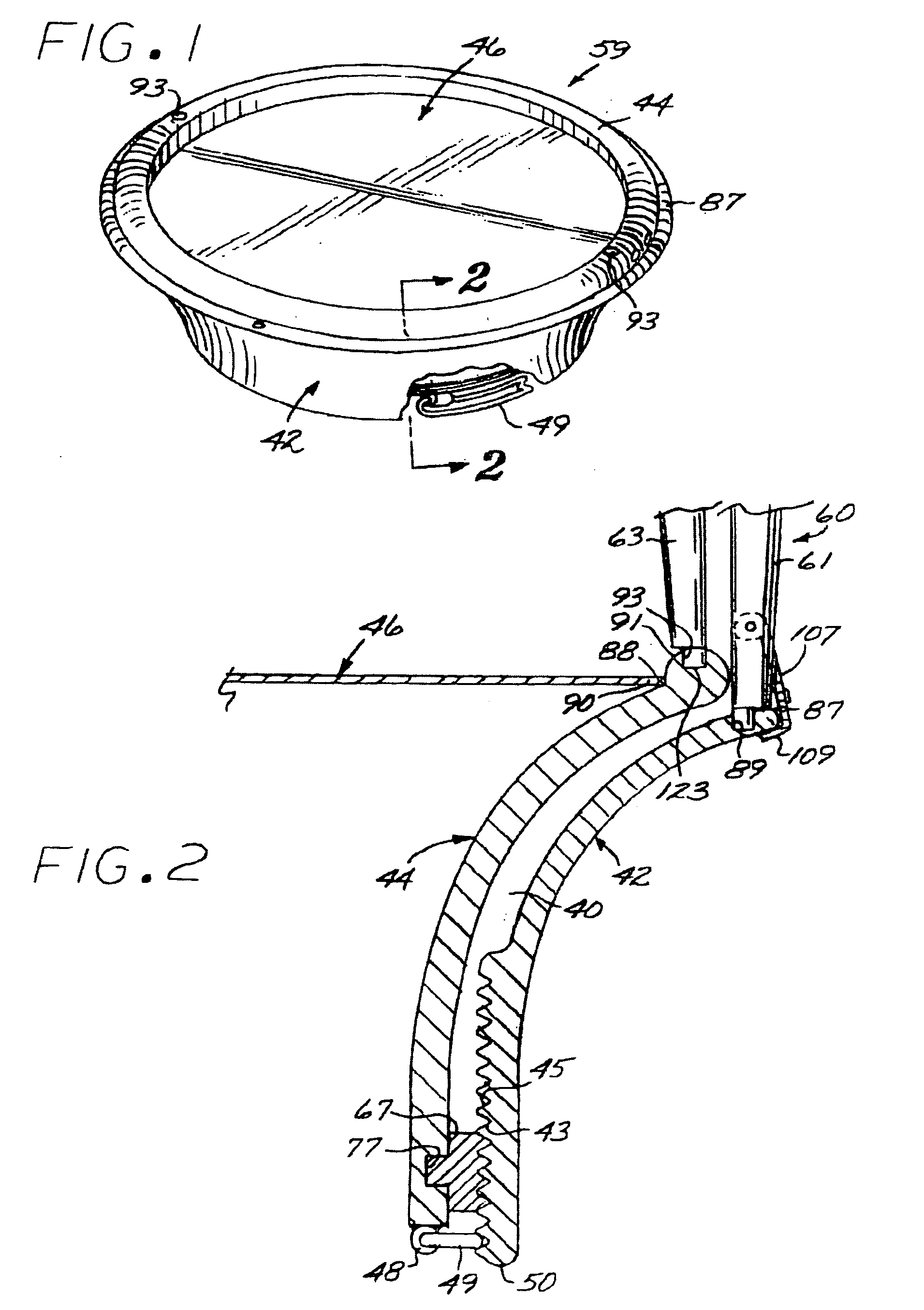
Figure 2 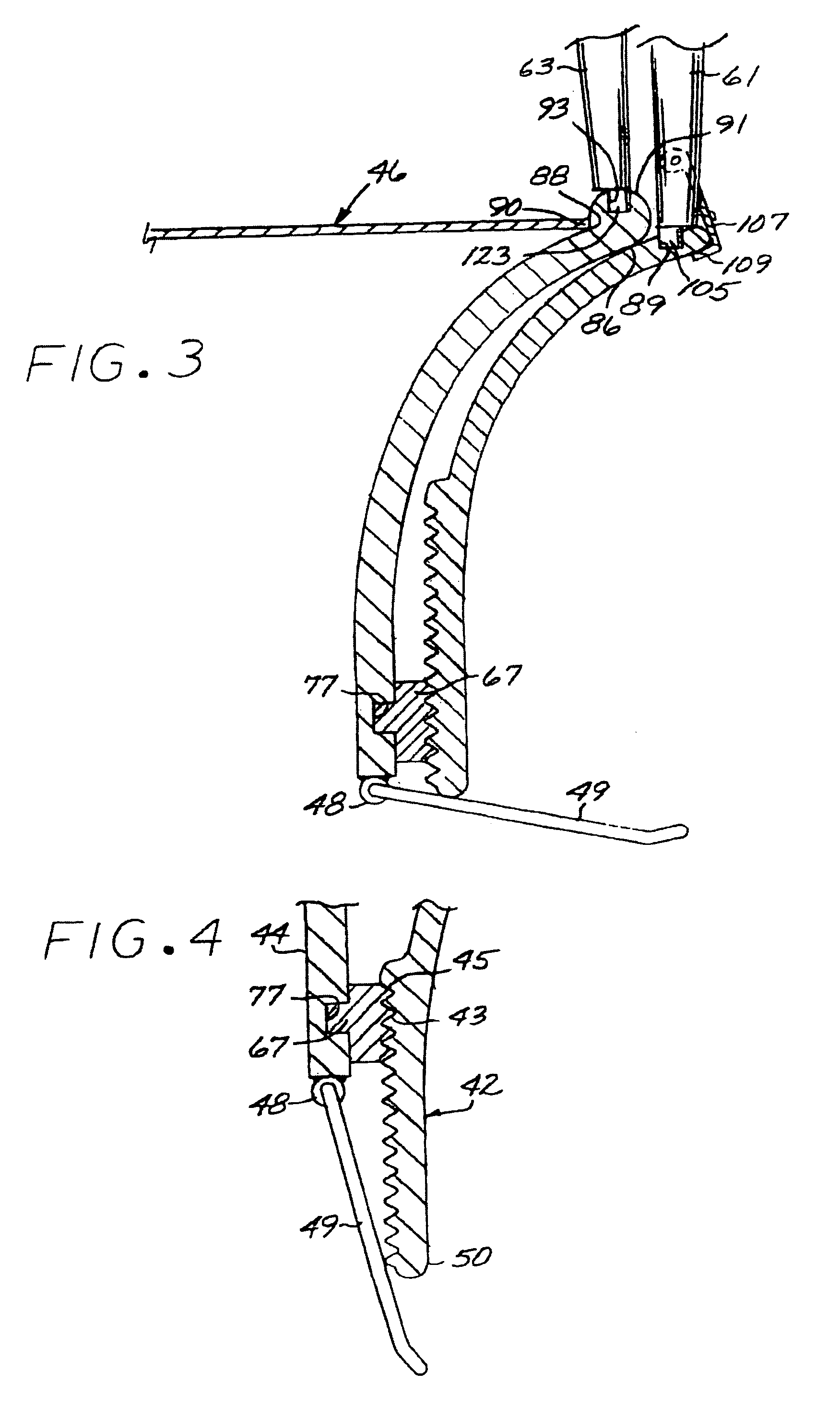
Figure 3
Abstract
Description
RELATED APPLICATION
[0001] This application is a divisional of co-pending U.S. application Ser. No. 09 / 666,617, filed 20 Sep. 2000, entitled “Heart Valve Annulus Device and Method of Using Same.”BACKGROUND OF THE INVENTION
[0002] 1. Field of the Invention
[0003] The present invention relates to a prosthetic heart valve anchor and a minimally invasive method for implantation.
[0004] 2. Description of the Prior Art
[0005] It has been estimated that up to 20% of all cardiac surgeries are directly related to valve replacement or implantation of artificial valves. It is well known that a variety of medical conditions and diseases may cause damage to the heart valve which ultimately necessitates valve replacement. Certain diseases such as rheumatic fever can cause the valve orifice to shrink or pull apart. If these defects are not corrected, prolonged valvular stenosis or insufficiency may cause damage to the heart muscle and may even require complete valve replacement. Other indications,...
Examples
second embodiment
[0062] Referring to FIGS. 11 through 13, the anchor apparatus of the present invention, shown without the prosthetic valve in place, includes, generally, a ring forming a band 131 having upper and lower ring elements 133 and 135. Interposed between the upper and lower ring elements 133 and 135 is an actuating ring, generally designated 134, configured with diamond shaped fold-inducing openings 137 spaced peripherally thereabout and configured and arranged to form therebetween axial panels 138 having their respective narrowest annular dimension on a circumferential line positioned to be, when the band is compressed axially splayed radially outwardly under the annulus shelf (FIG. 13) to cooperate in defining a retainer ring, generally designated 147. The ring may be constructed of a stressed metal covered with a biocompatible substance, or a semi-rigid plastic capable of a spring memory so that upon deployment, the anchor device will retain the axially shifted configuration without ad...
third embodiment
[0067] the prosthetic valve anchoring device of the present invention shown in FIGS. 16-18 without the prosthetic valve in place, includes a band, generally designated 201, somewhat similar to that shown in FIG. 11. The band 201 is formed with proximal and distal ring elements 203 and 205, respectively, and an actuator ring element 204 interposed between the proximal and distal elements. The distal ring element 205 is constructed with a retainer ring element, generally designated 200, having diamond shaped cut outs 202 spaced annularly apart to form said bands 206 which, when axial forces are applied, will splay radially outwardly to assume a diameter larger than that of the annulus to form an enlarged-in-diameter retainer.
[0068] Mounted about the interior of the proximal band element 203 are a plurality of rectangular latch brackets 207 configured with longitudinal passages. Corresponding elongated resilient latches, generally designated 211, are cantileverly mounted on the distal ...