Lighting device, and display apparatus providing lighting device

a technology of display apparatus and lighting device, which is applied in the direction of display means, television systems, instruments, etc., can solve the problems of increasing production costs and achieve the effect of reducing brightness non-uniformity and increasing production costs

Active Publication Date: 2011-05-12
SHARP KK
View PDF7 Cites 37 Cited by
  • Summary
  • Abstract
  • Description
  • Claims
  • Application Information

AI Technical Summary

Benefits of technology

[0013]The present invention has been made in view of the above problems, and it is an object of the present invention to provide a lighting device capable of reducing the nonuniformity of brightness and supporting handling various sizes and shapes without increasing the production cost.

Problems solved by technology

However, this would increase the production cost.

Method used


Image

  • Lighting device, and display apparatus providing lighting device
  • Lighting device, and display apparatus providing lighting device
  • Lighting device, and display apparatus providing lighting device

Examples


first embodiment

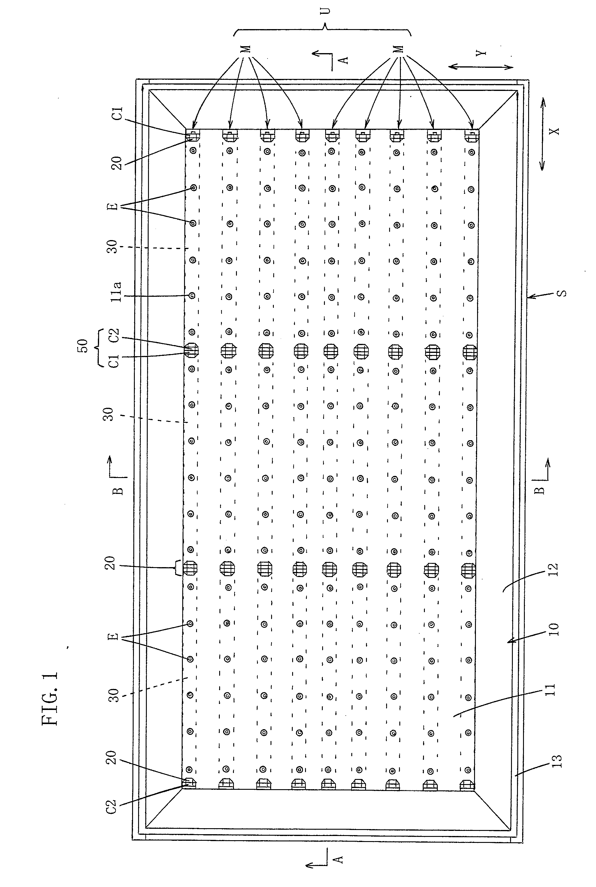
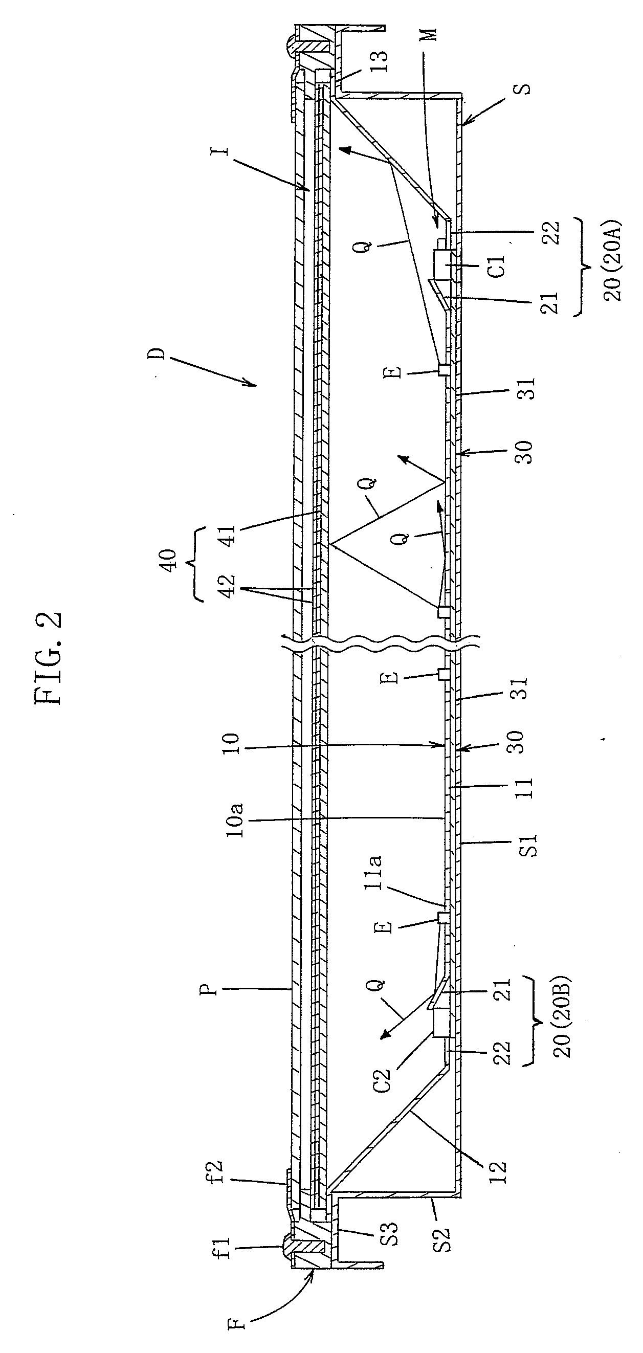
[0081]FIG. 1 is a plan view illustrating a first embodiment of a lighting device according to the present invention and a display apparatus using the lighting device. FIG. 2 is a cross sectional view taken along line A-A shown in FIG. 1, wherein an intermediate portion is not shown. FIG. 3 is a cross sectional view taken along line A-A shown in FIG. 1, wherein both end portions are not shown. FIG. 4 is a cross sectional view taken along line B-B shown in FIG. 1, wherein an intermediate portion is not shown.

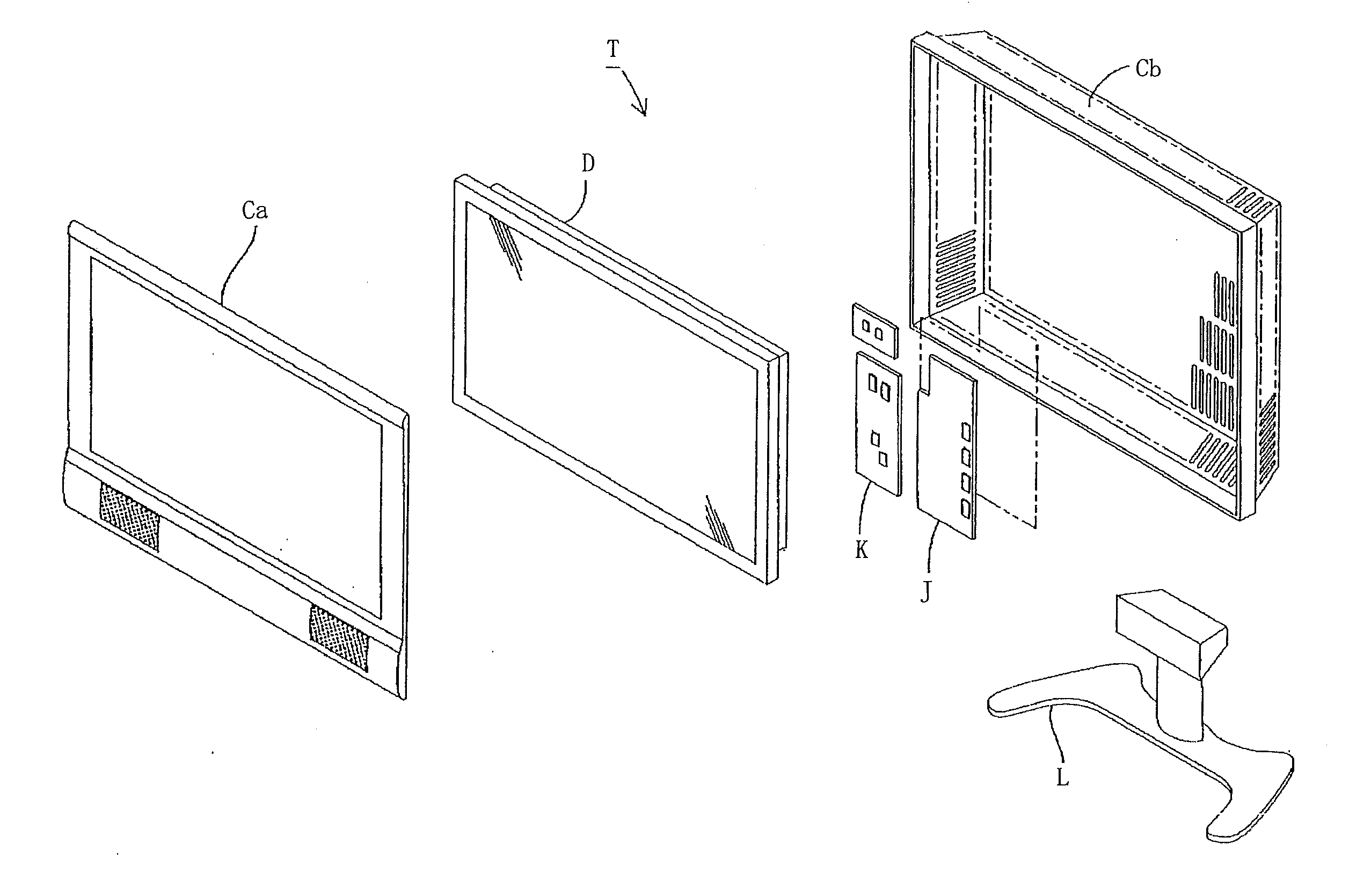
[0082]A lighting device I is used as a direct backlight device of a display apparatus D. The lighting device I includes a chassis S, a planar light emitting unit U housed in the chassis S, a reflection sheet 10 arranged on the light emitting surface side of the planar light emitting unit U, and a brightness nonuniformity reduction unit 20.

[0083]The planar light emitting unit U includes a plurality of light emitting modules arranged in parallel in the chassis S in a lateral directi...

second embodiment

[0149]FIG. 7 is a perspective view illustrating a portion of a second embodiment of a lighting device according to the present invention. FIG. 8 is a cross sectional view illustrating a portion of the lighting device according to the second embodiment, wherein both end portions are not shown. In FIG. 7 and FIG. 8, the same constituent elements as the constituent elements in FIG. 1 to FIG. 5 are denoted with the same reference numerals.

[0150]The second embodiment is the same as the first embodiment except for a brightness nonuniformity reduction portion 120. Hereinafter, portions of the second embodiment different from those of the first embodiment will be mainly described.

[0151]The brightness nonuniformity reduction unit 120 according to the second embodiment is structured according to the structure (B).

[0152]More specifically, the brightness nonuniformity reduction unit 120 includes bent covering portions 121 formed with cutouts in a portion of a reflection sheet 110 corresponding ...

third embodiment

[0160]FIG. 9 is a perspective view illustrating a portion of a third embodiment of a lighting device according to the present invention. FIG. 10 is a cross sectional view illustrating a portion of the lighting device according to the third embodiment, wherein both end portions are not shown. In FIG. 9 and FIG. 10, the same constituent elements as the constituent elements in FIG. 1 to FIG. 5 are denoted with the same reference numerals.

[0161]The third embodiment is the same as the first embodiment except for a brightness nonuniformity reduction portion 220. Hereinafter, portions of the third embodiment different from those of the first embodiment will be mainly described.

[0162]The brightness nonuniformity reduction unit 220 according to the third embodiment is structured according to the structure (C).

[0163]More specifically, the brightness nonuniformity reduction unit 220 includes an opening portion 222 formed in a portion of a reflection sheet 210 corresponding to first and second ...


PUM

PropertyMeasurementUnit
distanceaaaaaaaaaa
brightnessaaaaaaaaaa
transparentaaaaaaaaaa

Abstract

A lighting device comprising:
    • a light emitting module including a plurality of electrically connected light emitting bars each having a plurality of semiconductor light emitting devices;
    • a chassis for containing the light emitting module and having a discharge opening;
    • a reflection sheet arranged in the chassis; and
    • a brightness nonuniformity reduction unit,
    • wherein the light emitting bar includes:
    • a band plate-shaped substrate;
    • a wiring formed on one surface of the substrate;
    • the plurality of semiconductor light emitting devices; and
    • first and second connectors formed in proximity to opposing shorter sides on the one surface of the substrate,
    • wherein the reflection sheet has at least a plurality of corresponding holes through which the plurality of semiconductor light emitting devices are inserted,
    • and wherein the brightness nonuniformity reduction unit is arranged in proximity to a position of the first and second connectors of each light emitting bar.

Description

CROSS-REFERENCE TO RELATED APPLICATION[0001]This application is related to Japanese Patent Application No. 2009-254999 filed on Nov. 6, 2009, whose priority is claimed under 35 USC §119, the disclosure of which is incorporated by reference in its entirety.BACKGROUND OF THE INVENTION[0002]1. Field of the Invention[0003]The present invention relates to a lighting device, a display apparatus providing the lighting device, and a television receiver providing the display apparatus.[0004]2. Description of the Related Art[0005]Recently, a direct backlight LED lighting device (hereinafter referred to as “direct backlight device”) attracts people's attention. In the direct backlight device, light emitting diodes (hereinafter referred to as “LEDs”) are arranged on the entire back surface of a liquid crystal panel as a backlight of the liquid crystal display apparatus.[0006]The following direct backlight device has been suggested. In an LED module equipped with a plurality of LEDs arranged in ...

Claims


Application Information

Patent Timeline
Patent Type & Authority Applications(United States)
IPC IPC(8): H04N3/14F21S4/00G02F1/13357G02F1/1335
CPCG02F1/133605G02F1/133603G02F1/133608
Inventor TAKEMURA, HIDEO
Owner SHARP KK
Why Eureka
Try Eureka