Unlock instant, AI-driven research and patent intelligence for your innovation.

Polymer based joint implants and method of manufacture

a polymer and joint technology, applied in joint implants, prostheses, coatings, etc., can solve the problems of high material waste, prone to fracture, high cost, etc., and achieve excellent toughness and fatigue resistance.

Active Publication Date: 2016-11-03
THULIEZ JEAN LUC +1
View PDF2 Cites 1 Cited by
  • Summary
  • Abstract
  • Description
  • Claims
  • Application Information

AI Technical Summary

Benefits of technology

The technical effects of this patent are to create a device that has a surface with maximized crystallinity and density to mimic cortical bone. Additionally, the device should have a springiness close to natural biomechanical state and have a modulus of elasticity close to bone plus excellent toughness and fatigue resistance.

Problems solved by technology

Material waste is therefore high and may result in excessive costs.
It is, however, heavy, relatively expensive and prone to fracture upon impact.
In addition, geometric restrictions exist for this family of materials.
Metal alloys, when used in conjunction with polyethylene or ceramic, do function well, but concerns exist about polyethylene wear with a metal alloy counterpart due to the relatively high friction coefficient of this pairing.
Metal on metal bearings are currently causing great concern due to feared release of metal ions.
The greatest long-term impact on implant survival is, however, due to polyethylene wear.
The literature seems to suggest that the biggest cause of long-term implant loosening and ultimately implant failure is polyethylene wear.
When polyethylene debris is released into the joint capsule either due to friction wear or monomer particle release, giant cells called macrophages form around the debris, as the body is not capable of absorbing polyethylene debris.
As more macrophages form, the implant can become unstable and fail.
The present 3-phase manufacturing process of polymer synthesis in powder form, granulation in the form of beads, and extrusion into rods or sheets, followed by machining into the required shape, leads, however, to very high costs.

Method used


Image

  • Polymer based joint implants and method of manufacture
  • Polymer based joint implants and method of manufacture
  • Polymer based joint implants and method of manufacture

Examples


Embodiment Construction

[0045]The following description is not intended to limit the scope of the invention in any way as to they are exemplary in nature, serving to describe the best mode of the invention known the inventors as of the filing date hereof. Consequently, changes may be made in the arrangement and / or function of any of the elements described in the exemplary embodiments disclosed herein without departing from the spirit and scope of the invention.

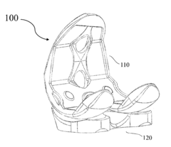
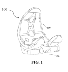
[0046]Thus, whereas the following description applies to the specific example of a tibial insert for a total knee replacement, the method can equally be applied to all kinds of orthopedic, cardio, neuro or any other implantable or non-implantable medical devices. Other examples are acetabular cup inserts for total hip replacement, and glenoid implants for total shoulder replacement, spinal implants, trauma implants.

[0047]All these devices have a number of features in common, such as a variable-density body with a wear resistant, dense outer surface, ...


PUM

PropertyMeasurementUnit
tensile strengthaaaaaaaaaa
relative thermal indexaaaaaaaaaa

Abstract

A method and implant based on injection molding techniques. The method produces polymeric components suitable for implantation with a structure and mechanical properties close to those of natural bone tissue. In a variant, method for making an implant or component thereof includes forming a standard shape foamed blank, and over-molding a thin layer of non-foamed PEEK material onto the standard shaped foamed blank to obtain a final implant component geometry, whereby the blank is completely encapsulated by the over-molded layer.

Description

CROSS REFERENCE TO RELATED APPLICATIONS[0001]This application claims the benefit of U.S. Provisional Application No. 61 / 787,270, filed 15 Mar. 2013, entitled: “POLYMER BASED IMPLANTS AND METHOD OF MANUFACTURE”, the contents of which are incorporated herein by reference thereto.COPYRIGHT & LEGAL NOTICE[0002]A portion of the disclosure of this patent document contains material which is subject to copyright protection. The Applicant has no objection to the facsimile reproduction by anyone of the patent document or the patent disclosure as it appears in the Patent and Trademark Office patent file or records, but otherwise reserves all copyright rights whatsoever. Further, no references to third party patents or articles made herein is to be construed as an admission that the present invention is not entitled to antedate such material by virtue of prior invention.FIELD OF THE INVENTION[0003]This invention relates to an economical method of creating medical implants with a mechanical stru...

Claims


Application Information

Patent Timeline
Patent Type & Authority Applications(United States)
IPC IPC(8): A61F2/30A61F2/38A61L27/30A61L27/44A61L27/18A61L27/56
CPCA61F2/30965A61L27/18A61L27/56A61L27/303A61L27/443A61F2/30A61F2002/30624A61F2/389A61L2430/24A61F2002/3863A61F2002/30971A61F2002/30016A61F2002/30011A61F2/3859A61L27/50A61L27/54A61L2300/104A61F2/3094A61F2/38A61F2310/0058C08L71/00
Inventor THULIEZ, JEAN-LUCAYLIFFE, JOHN NICHOLAS
Owner THULIEZ JEAN LUC