
Glow plug and method for connecting a pin made of functional ceramic to a metal sleeve
a technology of functional ceramics and glow plugs, which is applied in the direction of mechanical equipment, machines/engines, light and heating apparatus, etc., can solve the problems of premature failure of glow plugs and high mechanical properties, and achieve simple and cost-effective production of glow plugs, reliable and robust connection, and improved centered position.
- Summary
- Abstract
- Description
- Claims
- Application Information
AI Technical Summary
Benefits of technology
Problems solved by technology
Method used
Image

Examples
Embodiment Construction
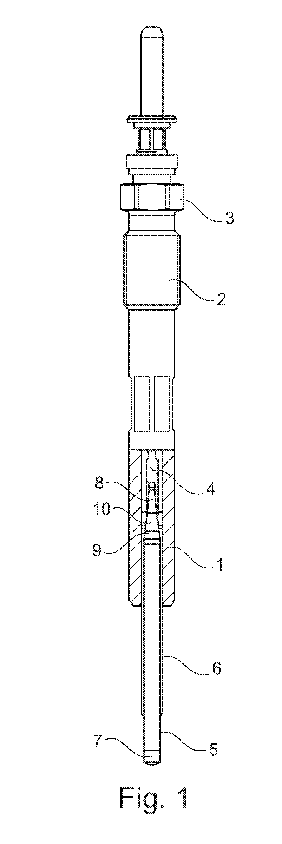
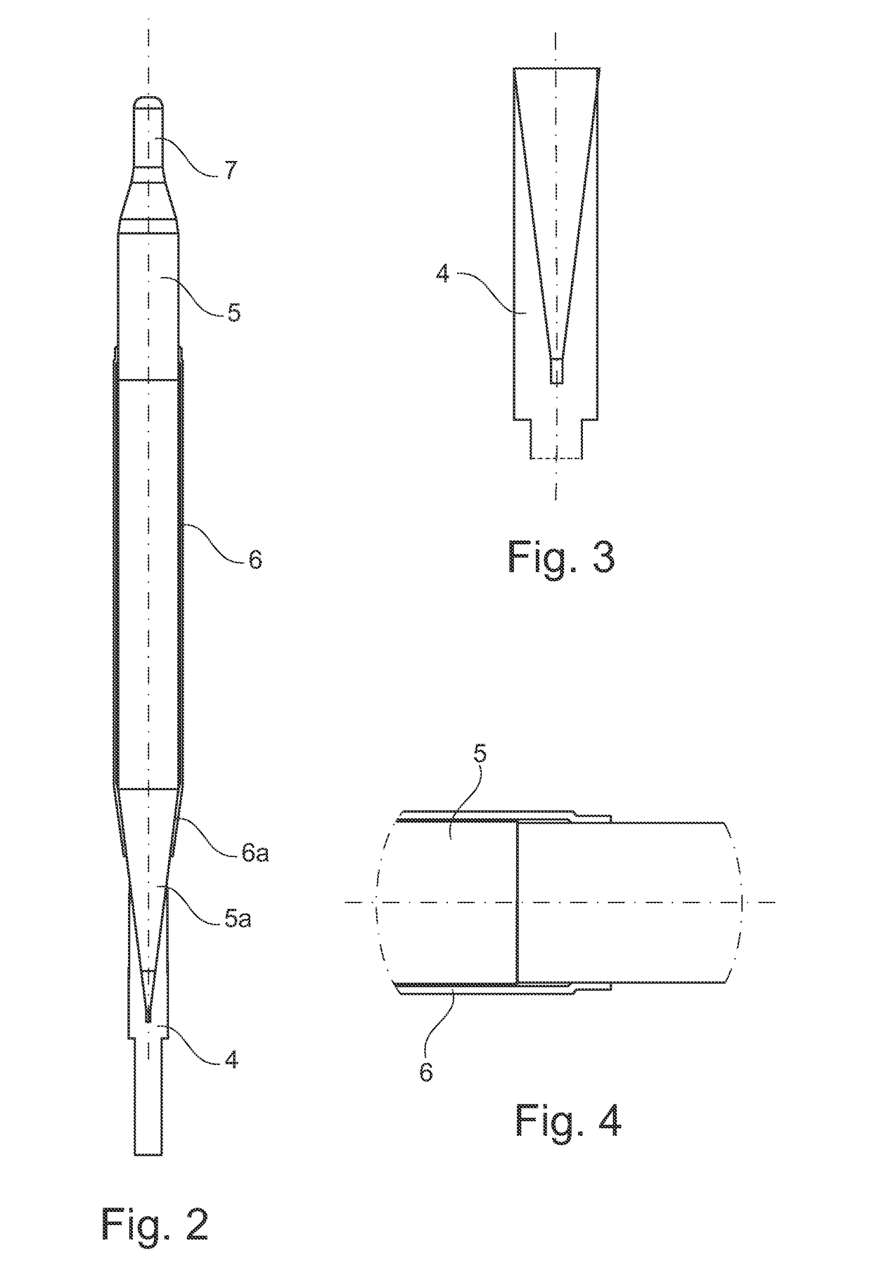
[0025]FIG. 1 is a schematic illustration of an exemplary embodiment of a glow plug in a partially cut view. The glow plug comprises a metallic housing 1 having an external thread 2 and a hexagon 3. In the housing 1, a metallic inner conductor 4 is disposed, which is connected to the rear end of a ceramic glow pin 5 facing away from the combustion chamber. The ceramic glow pin 5 is pressed into a metal sleeve 6, which is inserted into the housing 1. Both ends of the glow pin 5 protrude from the metal sleeve 6 and the glow pin has a glow tip 7 at the front end thereof on the combustion chamber side.
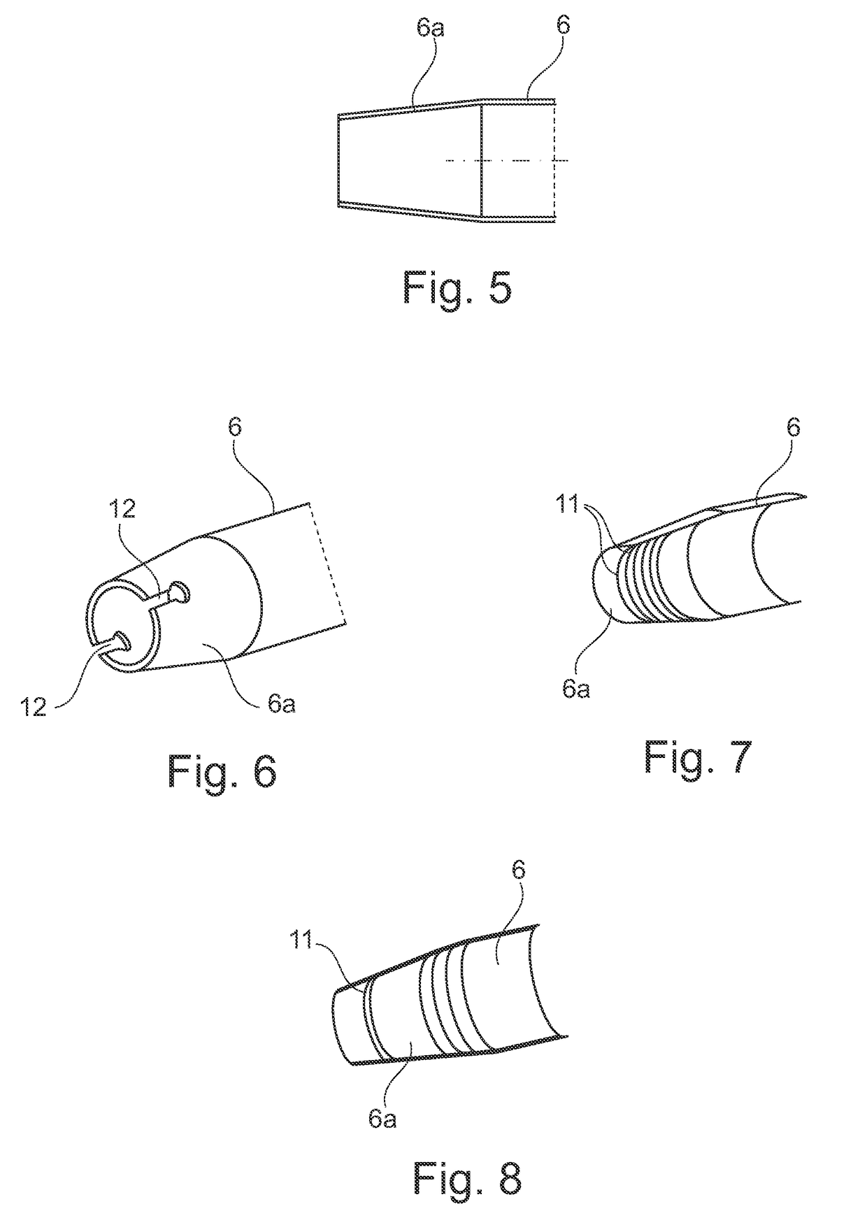
[0026]The metal sleeve 6 is preferably pressed into the housing, however it can also be brazed or welded to the housing 1, for example. At the front end, the rod-shaped metallic inner conductor 4 has an opening into which the rear end of the glow pin 5 projects. The rear end of the glow pin 5 is preferably pressed into the inner conductor 4. It is also possible, however, to braze the inner ...
PUM
| Property | Measurement | Unit |
|---|---|---|
| angle | aaaaa | aaaaa |
| diameter | aaaaa | aaaaa |
| bezel angles | aaaaa | aaaaa |
Abstract
Description
Claims
Application Information