

Pressure reducing valve and method thereof
A pressure reducing valve and disc technology, applied in the field of pressure reducing valves, can solve problems such as increased manufacturing costs, inability to respond to fluid pressure, complex design of pressure reducing valves, etc., to achieve stable guidance, increased life, and reduced axial rotational force Effect
Patent Information
- Authority / Receiving Office
- CN · China
- Patent Type
- Patents(China)
- Current Assignee / Owner
- Publication Date
- 2007-10-03
- Estimated Expiration
- Not applicable · inactive patent
Smart Images
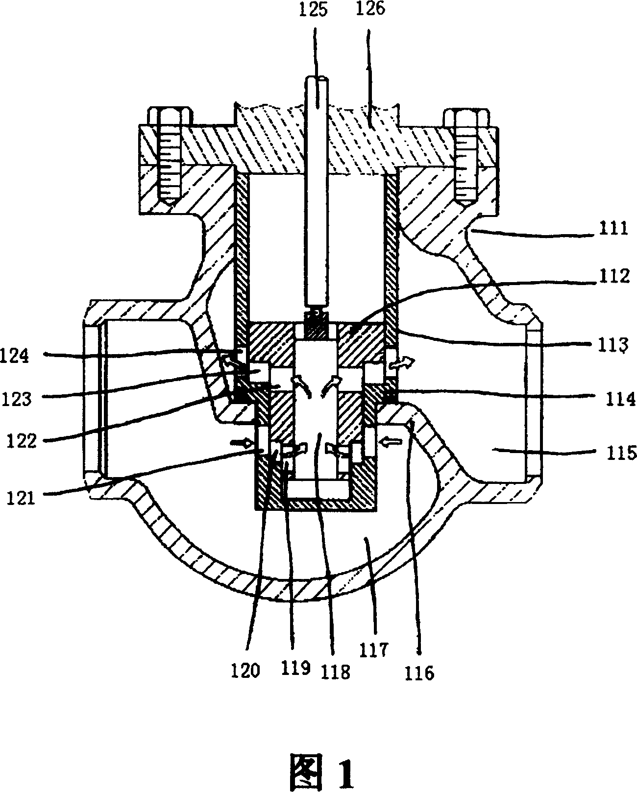
Figure 1 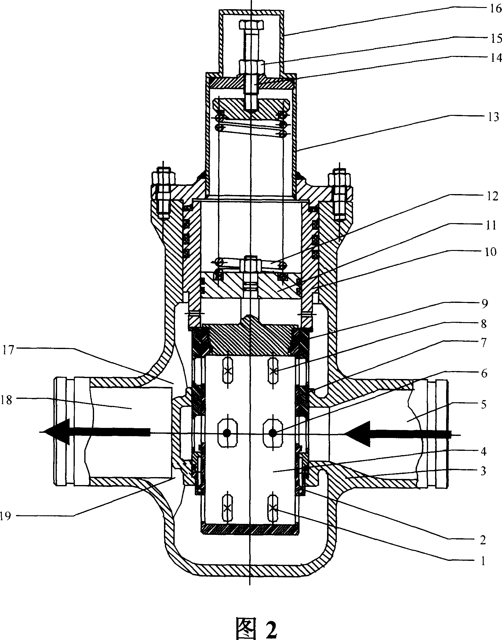
Figure 2 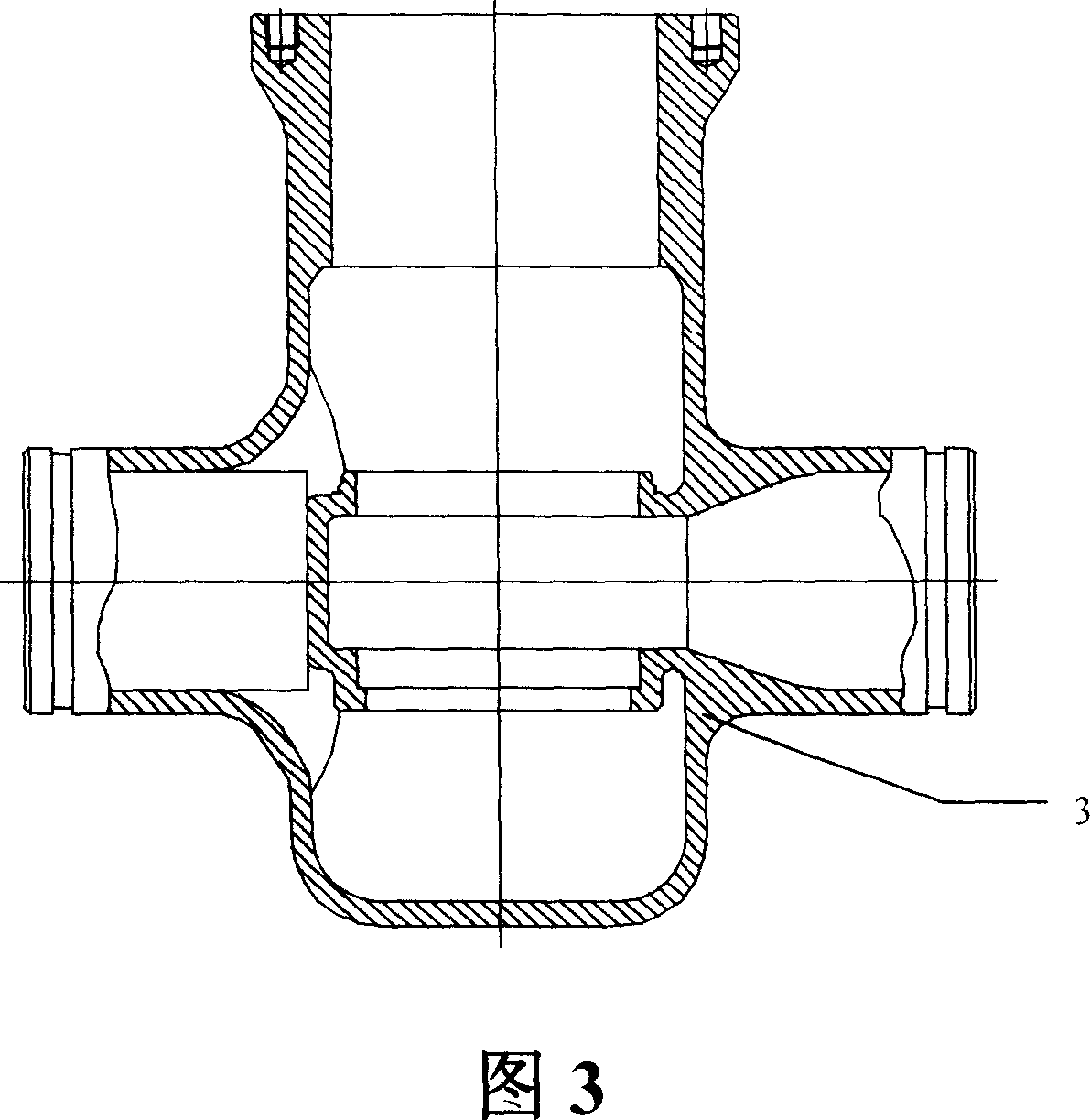
Figure 3
Abstract
Description
technical field
[0001] The invention relates to a pressure reducing valve for a fluid delivery system, in particular to a pressure reducing valve and a pressure reducing method for a high pressure drop system. The invention also relates to a fluid delivery system comprising the pressure relief valve described above. Background technique
[0002] The pressure reducing valve is to reduce the inlet pressure to a certain required outlet pressure by adjusting, so as to provide a certain pressure lower than the fluid pressure on the inlet side. The pressure reducing valve is installed on the pipeline leading to the fluid, regardless of the pressure of the fluid on the inlet side of the pressure reducing valve, it can maintain the fluid pressure on the outlet side at the required set pressure value.
[0003] From the point of view of fluid mechanics, the pressure reducing valve is a throttling element whose local resistance can be changed, that is, by changing the throttling area,...
Examples
Embodiment Construction
[0105] The preferred embodiments of the present invention will be described in detail below in conjunction with the accompanying drawings.
[0106] Fig. 2 is a schematic diagram showing the structure of a pressure reducing valve according to a specific embodiment of the present invention.
[0107] As shown in FIG. 2 , the pressure reducing valve according to the present invention mainly includes a valve body 3 , a valve core 4 and the like. The valve body 3 and the valve core 4 jointly define a fluid channel with two stages of throttling, and the channel connects the inlet 5 and the outlet 18 .
[0108] In practical applications, both ends of the valve body 3 of the pressure reducing valve are connected (eg, welded) to the fluid inlet and outlet joints of pipelines or equipment, wherein the inlet 5 of the valve body 3 is connected to a fluid pressure source (not shown). The machining dimensions above the mating surface of the valve seat 2 in the vertical direction of the inne...