
Resonant DC/DC converter and its control method
A DC converter, resonant DC technology, applied in the direction of conversion equipment with intermediate conversion to AC, can solve the problem of frequency modulation control being difficult to stabilize, and achieve the effect of increasing the output voltage regulation capability and expanding the voltage output range
Patent Information
- Authority / Receiving Office
- CN · China
- Patent Type
- Patents(China)
- Current Assignee / Owner
- Publication Date
- 2012-06-27
Smart Images
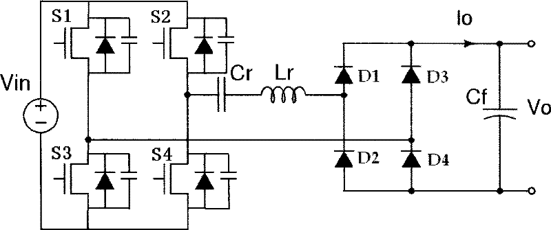
Figure 1 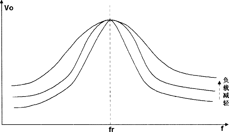
Figure 2 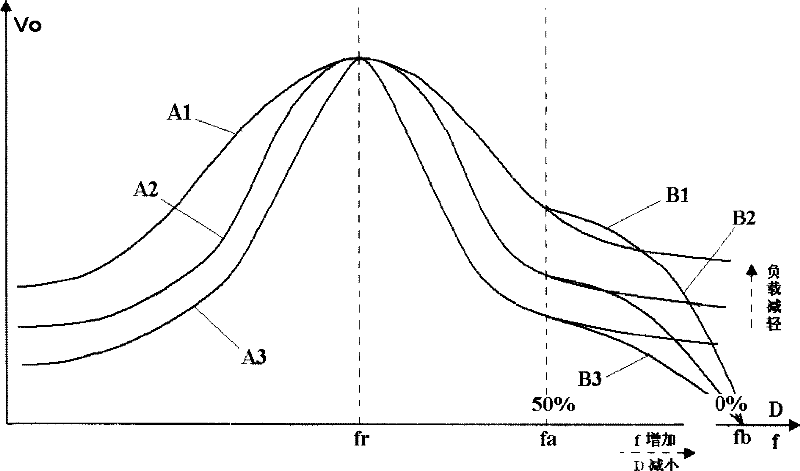
Figure 3
Abstract
Description
Technical field
[0001] The invention relates to DC power conversion technology, in particular to a resonant DC / DC converter and a control method thereof.
Background technique
[0002] Miniaturization and high frequency are the development trend of power supply today, but the increase of switching frequency has brought about the problem of excessive loss of the switching tube, which cannot be solved by the traditional BUCK converter, but the resonant converter can better solve it this problem.
[0003] Taking the series resonant converter as an example, the series resonant DC / DC (DC / DC) converter adopts resonant conversion technology. Since the resonant element works in a sinusoidal resonance state, the voltage on the switching tube naturally crosses zero, which can realize zero-voltage turn-on. The loss is very small. This topology usually adopts a pulse frequency modulation (PFM) method to stabilize the output voltage by changing the operating frequency. figure 1 It ...
Examples
Embodiment Construction
[0046] A control method of a resonant DC / DC converter is to adjust the output voltage by changing the conduction frequency of the input switching tube of the resonant circuit, and also according to the feedback signal of the load circuit (obtained from the output voltage or output current sampling of the resonant converter) ) to adjust the phase shift angle of the switching tube, so that the voltage output range of the resonant circuit is expanded.
[0047] still with figure 1 Take the full-bridge series resonant circuit in the example, image 3 Curves A1~A3 in the figure are schematic diagrams of characteristic curves of output voltage Vo and frequency f with a phase shift angle of 0 degrees under different load conditions using separate PFM control mode. It can be seen that as the load is reduced, Vo tends to be flat. It is difficult to stabilize by increasing the operating frequency. image 3 The curves B1, B2, and B3 in the curves are respectively the characteristic curv...