
Yarn winding machine and yarn winding method
A winding machine and yarn technology, which is applied in the field of yarn winding machines, can solve problems such as damaged effects and inability to eliminate bulging phenomena, and achieve the effect of eliminating convex edge winding and eliminating bulging phenomena
Patent Information
- Authority / Receiving Office
- CN · China
- Patent Type
- Patents(China)
- Current Assignee / Owner
- Publication Date
- 2012-10-24
Smart Images
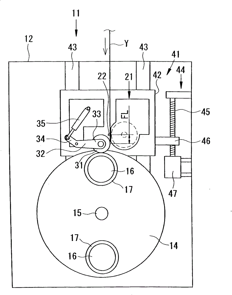
Figure 1 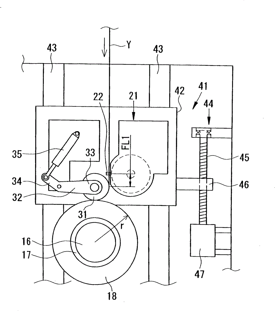
Figure 2 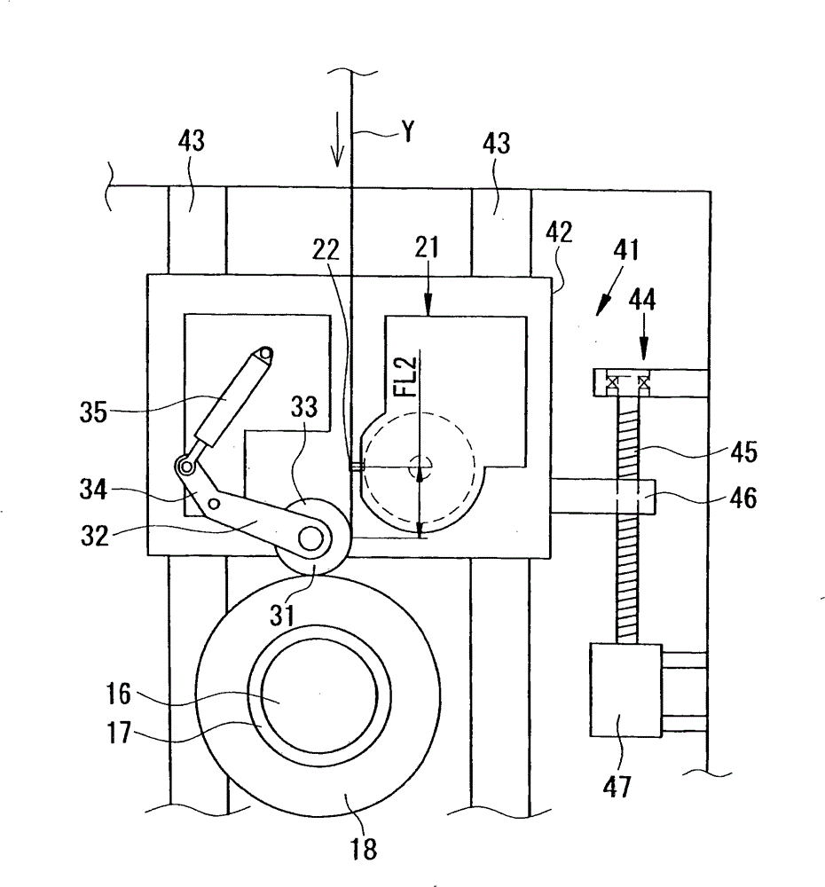
Figure 3
Abstract
Description
technical field
[0001] The present invention relates to a yarn winding machine and a yarn winding method for winding yarn, such as synthetic fiber yarn, onto a bobbin to form a package. Background technique
[0002] For example, a yarn winder that is a yarn winder is provided with a traverse guide device including a traverse guide that reciprocates in the axial direction of the bobbin. In addition, a structure is adopted in which the bobbin is rotated while contacting the touch roller or the friction roller, and the package is wound up while cross-winding the yarn. However, since the yarn density is concentrated at the turn-back parts of the yarn at both ends of the package, there is a problem that the package ends are raised higher than the center portion (ear height), and the package becomes drum-shaped. If the raised portion occurs, there is a problem of unwinding failure when the yarn is unwound from the package in the subsequent process.
[0003] In order to eliminate...
Examples
Embodiment 1
[0037] like figure 1 As shown, the winder 11 includes a body frame 12 on which a slide box 42 that can be raised and lowered relative to the body frame 12 and a turntable plate 14 that is rotatable relative to the body frame 12 are provided. The turntable plate 14 can rotate around the rotating shaft 15 under the drive of a rotating drive device (not shown in the figure). Two bobbin holders (bobbin holders) 16 to which bobbins 17 are attached protrude from positions symmetrical to the rotation axis 15 of the turntable plate 14 . By reversing the turret plate 14 with the rotary drive unit, the positions of the two bobbin holders 16 can be exchanged so that one of the bobbin holders 16 is located at the upper winding position and the other is located at the lower standby position.
[0038] like Figure 4 As shown, two bobbin holders 16 provided on the turret plate 14 are respectively connected to bobbin holder drive motors 19 so as to be rotatable. Each bobbin holder drive m...
Embodiment 2
[0064] The knurling suppression mechanism is a well-known mechanism in the prior art, and is to eliminate the knurling of the package 18 like Figure 9 This is a mechanism for gradually changing the diagonal weave angle in the early stage P2 and the late stage P3 of the package forming period P1 as shown. The twill angle at this time is the reference twill angle A1 determined by upper factors such as the type of synthetic fiber yarn Y. Therefore, the burr suppression mechanism is a mechanism for changing the reference diagonal angle A1. In the early stage P2 of the package forming period P1, the convex edge suppression mechanism starts winding from a small reference twill angle A1, gradually increases the reference twill angle A1, and gradually decreases to a small reference twill angle A1 in the later stage P3 until the end of winding . The knuckle suppression mechanism is a mechanism that changes the density of the package 18 from high density to low density in the early s...