
Dual-yoke type heavy steel pile trolley for cutter suction dredge
A technology for a cutter suction dredger and a steel pile trolley, which is applied to the device field in the field of marine engineering technology, can solve the problems of increased external force of the trolley system, inability to adapt to the trolley system, increased track deformation, etc. The effect of large force, strong track deformation adaptability and prolonging service life
Patent Information
- Authority / Receiving Office
- CN · China
- Patent Type
- Patents(China)
- Current Assignee / Owner
- Publication Date
- 2011-01-19
- Estimated Expiration
- Not applicable · inactive patent
Smart Images
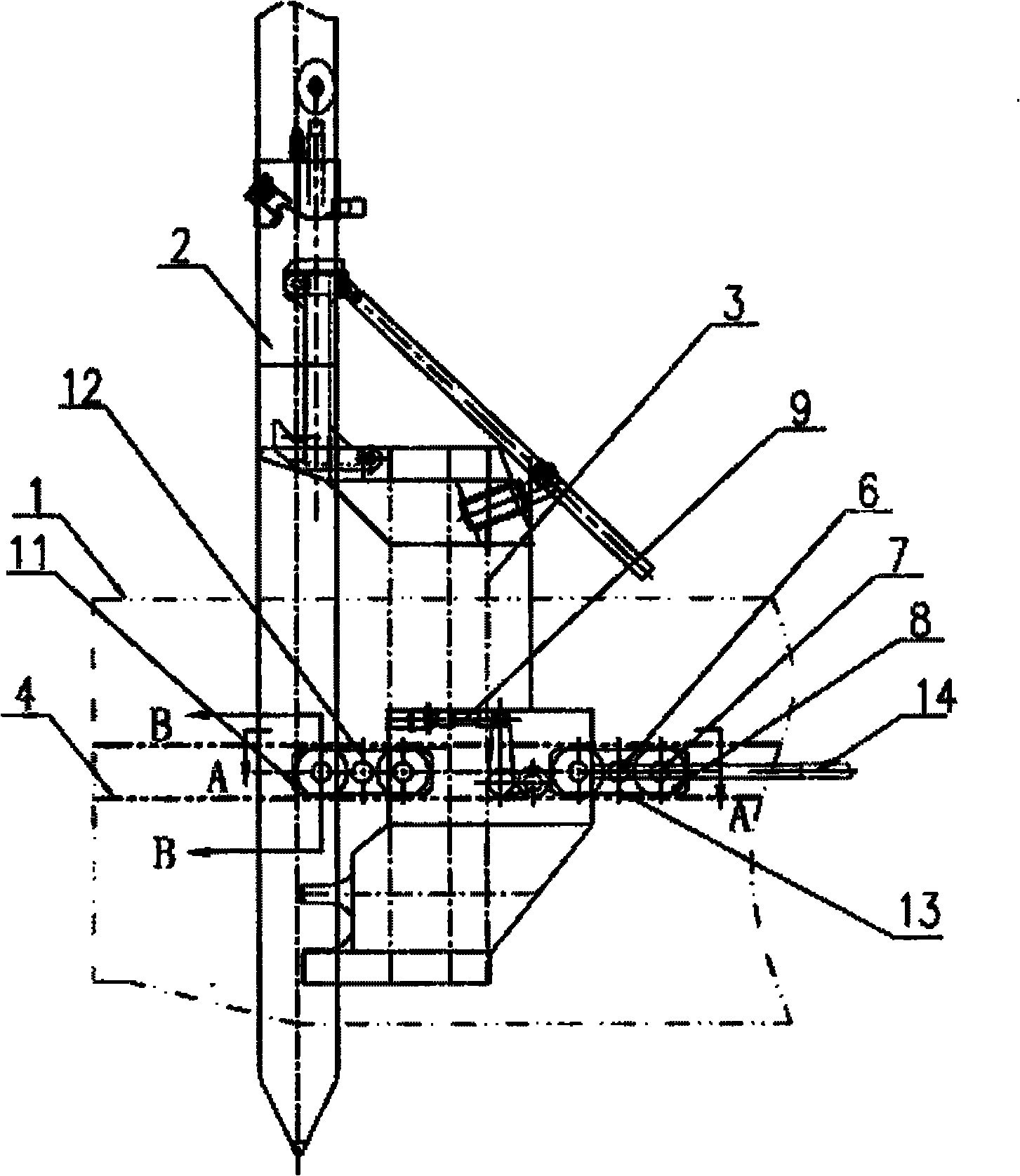
Figure 1 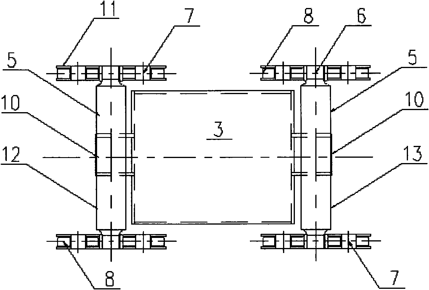
Figure 2 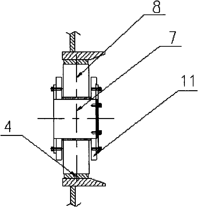
Figure 3
Abstract
Description
technical field
[0001] The invention relates to a device in the technical field of marine engineering, in particular to a double-yoke type heavy-duty steel pile trolley for a cutter suction dredger. Background technique
[0002] Modern large-scale cutter suction dredgers usually use a steel pile trolley system for shifting. The trolley system moves through the push and pull of the traveling cylinder, and sends an instruction signal through the trolley stroke to accurately control the forward distance, which can greatly save time and significantly improve production efficiency.
[0003] After searching the literature of the prior art, it was found that Jiang Ruhong and others published "Design and Research of Large Cutter Suction Dredger Trolley System" on page 41 of the 3rd issue of "Ship Engineering" in 2007. The system principle and composition of the positioning device of the suction dredger trolley, among which the walking subsystem is composed of walking cylinders, fro...
Examples
Embodiment Construction
[0022] The embodiments of the present invention are described in detail below in conjunction with the accompanying drawings: this embodiment is implemented on the premise of the technical solution of the present invention, and detailed implementation methods and specific operating procedures are provided, but the protection scope of the present invention is not limited to the following the described embodiment.
[0023] Such as figure 1 , figure 2 with image 3 As shown, this embodiment includes: hull 1, steel pile 2, trolley main structure 3, track 4, balance beam 5, wall frame rotating shaft 6, roller rotating shaft 7, walking roller 8, buffer device 9, balancing beam rotating shaft 10, Roller wall frame 11, first traveling yoke 12, second traveling yoke 13, and traveling oil cylinder 14. The first walking yoke 12 is exactly the same as the second walking yoke 13, and the walking yoke includes four identical walking rollers 8, roller rotating shaft 7, wall frame rotating...