
Low-disturbance sealing device for sediment sampler
A technology of sealing device and sampler, which is applied in the direction of sampling device, etc., can solve the problems of sample loss, sampling failure, sediment disturbance, etc., and achieve the effect of simple operation, light weight and small volume
Patent Information
- Authority / Receiving Office
- CN · China
- Patent Type
- Patents(China)
- Current Assignee / Owner
- Publication Date
- 2011-08-10
- Estimated Expiration
- Not applicable · inactive patent
Smart Images
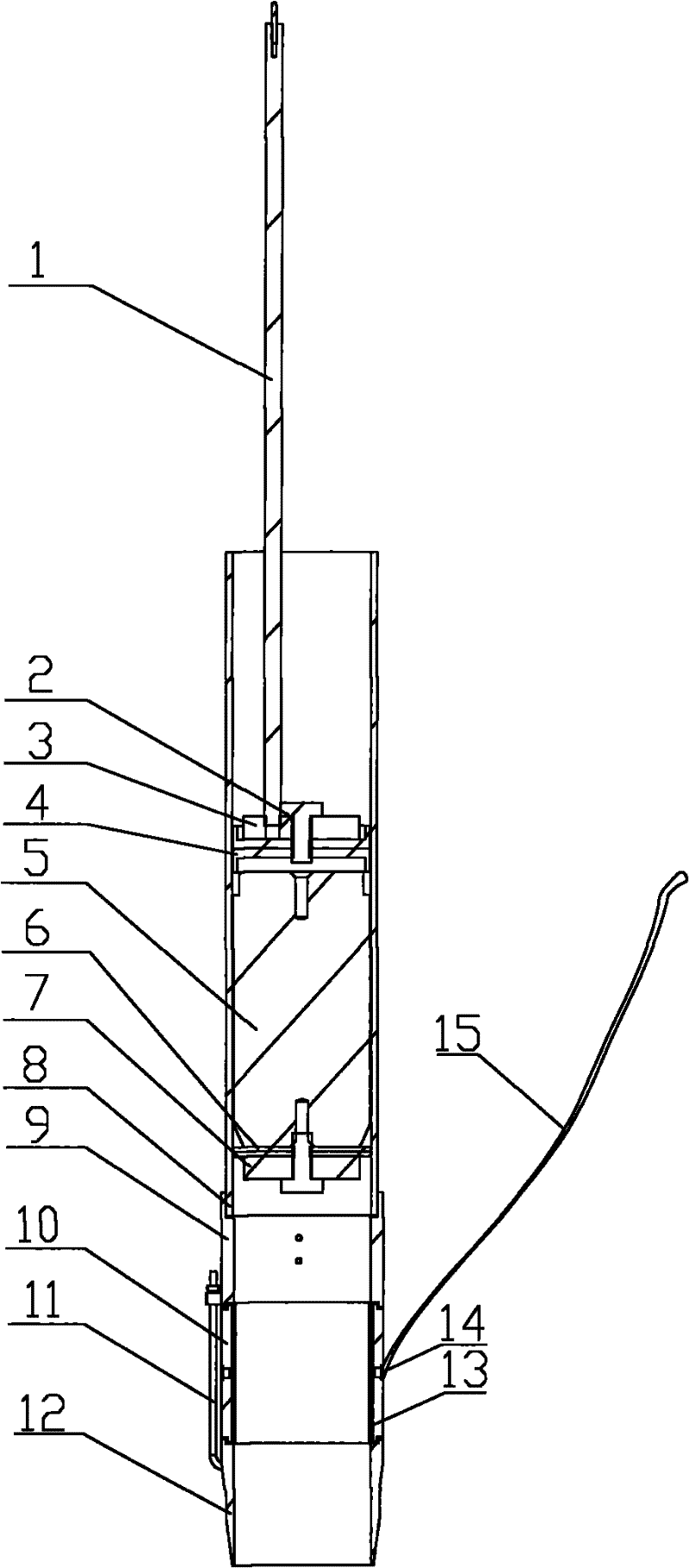
Figure 1 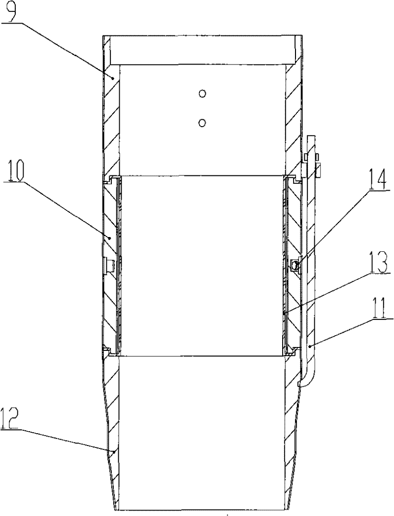
Figure 2 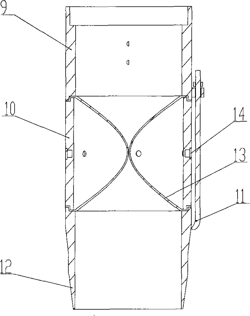
Figure 3
Abstract
Description
technical field
[0001] The invention belongs to the technical field of underwater sediment and overlying water sampling, and in particular relates to a low-disturbance sealing device for a sediment sampler. Background technique
[0002] In the low-disturbance sediment sampling process in shallow waters, one of the key technologies is to implement low-disturbance effective sealing of the sampling device. If the nozzle at the upper end of the sampling cylinder cannot be effectively sealed, it will cause the sediment to slip out of the sampling cylinder during the process of pulling out water on the sampler, causing the sample to be lost, and also affecting the hierarchical structure of the sample, resulting in sampling failure. If the bottom of the sampling cylinder is not sealed tightly, due to the weight of the sediment, the sampler will also lose the sample during the lifting process, which will also affect the hierarchical structure of the sample and cause sampling failure...
Examples
Embodiment Construction
[0016] The present invention will be further described below in conjunction with accompanying drawing.
[0017] Such as figure 1 As shown, a low-disturbance sealing device for a sediment sampler includes two parts: a piston sealing mechanism and an air sealing mechanism:
[0018] 1) Piston sealing mechanism: including piston rod 1, bolt 2, upper support flange 3, sealing ring 4, piston 5, sealing ring 6, lower support flange 7 and sampling cylinder 8. The piston mechanism forms the upper port seal of the sampling cylinder 8, the two ends of the sampling cylinder 8 are open, the piston 5 is movable in the sampling cylinder, the top of the piston is sequentially provided with the sealing retaining ring 4 and the upper supporting flange 2, and the upper supporting flange 2. The sealing retaining ring 4 and the piston 5 are fixedly connected by bolts 2, and one end of the piston rod 1 is fixedly connected with the upper supporting flange 3 by threads; the bottom of the piston 5 i...