
Distributor with circular outlet
An outlet distributor, circular technology, applied in the field of fluid distributors, can solve the problem of inability to realize co-extrusion in production
Patent Information
- Authority / Receiving Office
- CN · China
- Patent Type
- Applications(China)
- Current Assignee / Owner
- Publication Date
- 2017-05-24
- Estimated Expiration
- Not applicable · inactive patent
Smart Images
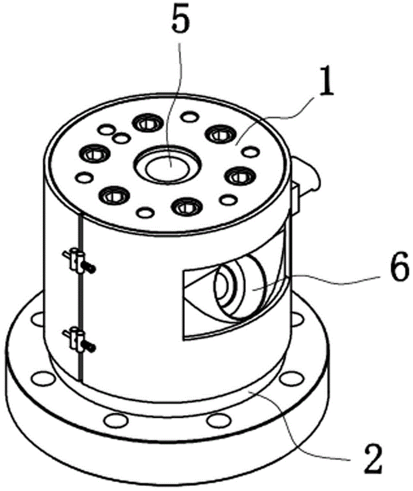
Figure 1 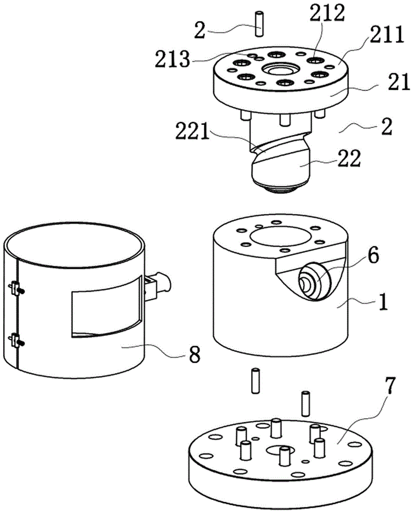
Figure 2 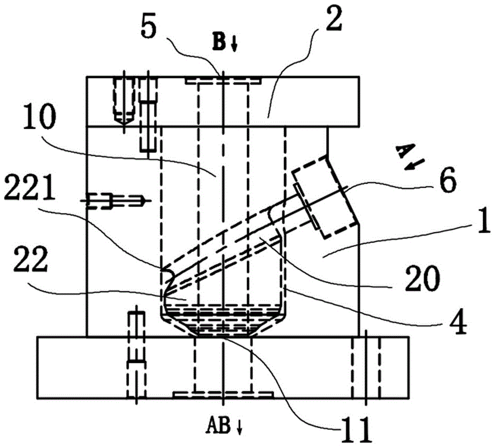
Figure 3
Abstract
Description
technical field
[0001] The invention relates to a fluid distributor, in particular to a fluid distributor used in the production of plastic sheets and film extrusion production lines and installed between an extruder and an extrusion die head. Background technique
[0002] A common fluid distributor includes a mold body and a shunt mandrel. The shunt mandrel is built into the mold body. The main feed port and the auxiliary feed port are connected to the main flow channel and the auxiliary machine flow channel in the mold. The fluid flows through the main machine. After the channel and the auxiliary machine channel are diverted into their respective layered channels by the diverter mandrel, the thickness of each layer of fluid is adjusted through an adjustment device, such as a swing leaf or a paddle, so as to achieve a layered structure with different thicknesses. Fluids converge from each layered channel and come out from the final outlet of the main channel, and finally ma...
Examples
Embodiment Construction
[0018] The present invention will be further described below in conjunction with accompanying drawing.
[0019] Such as Figure 1~5 As shown, the circular outlet distributor includes a main body 1 and a shunt mandrel 2, the shunt mandrel 2 is built in the main body 2, one end of the shunt mandrel 2 is a fixed end 21, and the fixed end 21 has a fixed protrusion The edge 211 and the fixing hole 212, the fixed end 21 of the shunt mandrel is matched with the end face of the main body 1 through the positioning pin 3 and the positioning hole 213, and the shunt mandrel 2 and the main body 1 are positioned and then installed into the fixing hole 212 with fixing screws Fasten the two connections.
[0020] Such as figure 2 , 3 As shown, the other end of the splitter mandrel 2 is a cylindrical rod body 22, the front end of the cylindrical rod body 22 is conical. , the auxiliary machine runner groove 221 spirally extends downward toward the outlet. There is a certain gap 4 between t...