
Visualized medical auxiliary inspection equipment
A technology for auxiliary inspection and equipment, applied in the field of medical devices, can solve the problems of no objective file, high cost, single function, etc., and achieve the effect of simple and compact internal structure, lower production cost, and single optical element
Patent Information
- Authority / Receiving Office
- CN · China
- Patent Type
- Applications(China)
- Current Assignee / Owner
- Publication Date
- 2010-09-15
- Estimated Expiration
- Not applicable · inactive patent
Smart Images
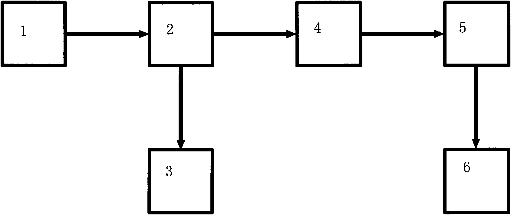
Figure 1 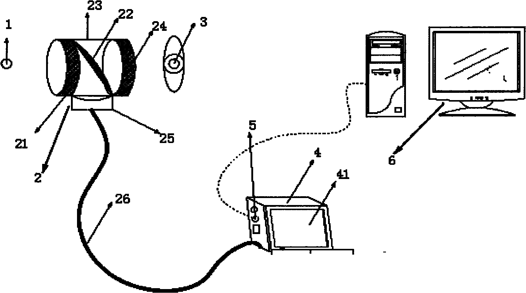
Figure 2 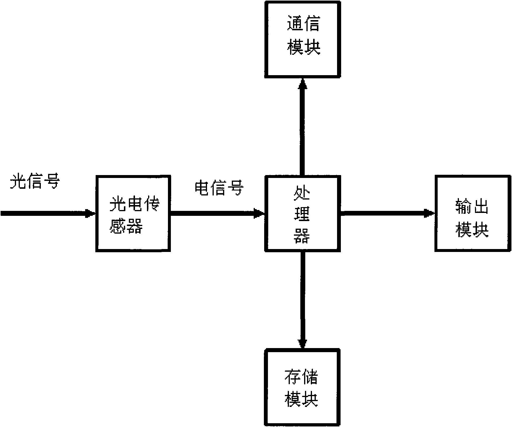
Figure 3
Abstract
Description
Technical field
[0001] The invention belongs to the field of medical devices, in particular to a visual medical auxiliary inspection device. Background technique
[0002] Due to the failure of basic inspection equipment such as frontal mirror, indirect laryngoscope, ophthalmoscope, and retinoscopy to save the images seen, it is common for departments such as otolaryngology, ophthalmology, and stomatology that most diagnostic evidence cannot be saved. In case analysis, telemedicine, etc. , scientific research, and medical dispute handling have no objective archives to refer to. At the same time, most of these devices can only be watched independently by observers, and there are many inconveniences in the teaching process. When teaching a certain inspection method, the teacher cannot demonstrate it to multiple people at the same time. Although existing equipment such as electronic laryngoscopes and fundus cameras can capture image data, the equipment is bulky, single-function...
Examples
Embodiment Construction
[0012] see figure 1 , figure 2 and image 3 , the present invention comprises observation system 2 and imaging device 4, and the housing of observation system 2 is a cylindrical shape, and beam splitter 22 is arranged in the housing, and the two ends of housing are respectively provided with eyepiece 24 and objective lens 21, and mechanical support 23 is provided with On the periphery of the housing, the optical fiber connector 25 is arranged on the lower side of the housing and is connected with the optical fiber 26; the imaging device 4 is provided with an LCD display 41, and the imaging device 4 is connected with the other end of the optical fiber 26, and the output of the imaging device 4 , the communication interface 5 is connected with several displays or computer equipment 6 . The mechanical support 23 is fixed on the frenulum. The observed scene 1 is divided into two beams by the beam splitter 22 through the observation system 2, one beam is injected into the obser...