
Experiment design and analysis method for most severe current stress born by thyristor used for converter valve
A technology of current stress and analysis method, which is applied in the direction of circuit breaker testing, single semiconductor device testing, etc. It can solve the problems of different thyristor current stress, unsatisfactory requirements, and inconsistent current waveforms, etc., and achieves simple implementation, easy adjustment, and simulation. simple effect
Patent Information
- Authority / Receiving Office
- CN · China
- Patent Type
- Applications(China)
- Current Assignee / Owner
- Publication Date
- 2011-02-23
Smart Images
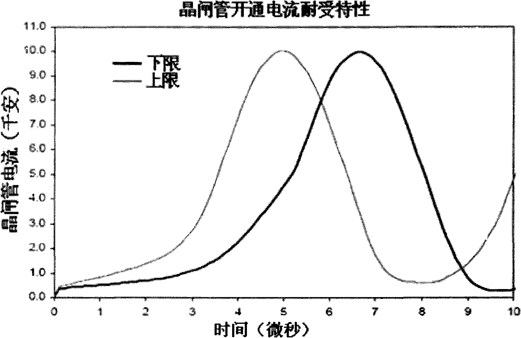
Figure 1 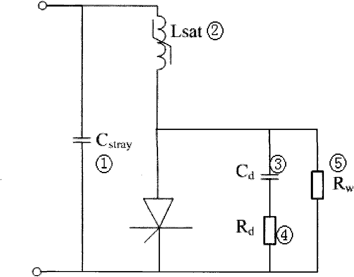
Figure 2 
Figure 3
Abstract
Description
technical field
[0001] The invention relates to the field of power system devices, in particular to an experiment design and analysis method for thyristors used in converter valves to withstand the most severe current stress. Background technique
[0002] Thyristors for DC transmission converter valves are the most critical and core devices in converter valves. During the operation of the converter valve, the voltage and current stresses on the thyristor need to be within its safe operating range to ensure the normal operation of the thyristor. Among the current stresses that the thyristors should be able to withstand, the most severe transient current stress is the current caused by the transfer of the energy of the arrester and the energy of the stray capacitance between the valve terminals through the thyristor when the converter valve is triggered acyclically (according to IEC and GB). stress.
[0003] Generally, the bridge arm of the converter valve is composed of doz...
Examples
Embodiment Construction
[0032] The present invention adopts the following sequence to realize the test design and process of the thyristor used in the converter valve to withstand the most severe current stress:
[0033] (1) Non-periodical triggering condition of the converter valve;
[0034] When the converter valve is subjected to non-periodic triggering conditions, the typical current waveform flowing through the thyristor is as follows: Figure 1 shown.
[0035] (2) Thyristor current test circuit;
[0036] The present invention names this test as the non-repetitive trigger current test, and the purpose is to produce and Figure 1Equivalent current stress, and the parameter adjustment of the test circuit should be simple and convenient, and the test object is a single thyristor.
[0037] The schematic diagram of the test circuit is as Figure II shown. where the discharge capacitor C stray pre-charged to Uo, saturable reactor L sat It is equivalent to a saturated reactor connected to a sing...