
Mechanical pressure regulation type electric pressure cooker
An electric pressure cooker and pressure-regulating technology, which is applied in pressure cookers and other directions, can solve the problems affecting the accuracy of the adjustment of the flash switch, the looseness of the arm body at the fixed point, and the complexity of the adjustment mechanism, etc., and achieve high precision of displacement signal transmission and sensitive action , The effect of simple driving structure
Patent Information
- Authority / Receiving Office
- CN · China
- Current Assignee / Owner
- Publication Date
- 2011-10-26
- Estimated Expiration
- Not applicable · inactive patent
Smart Images
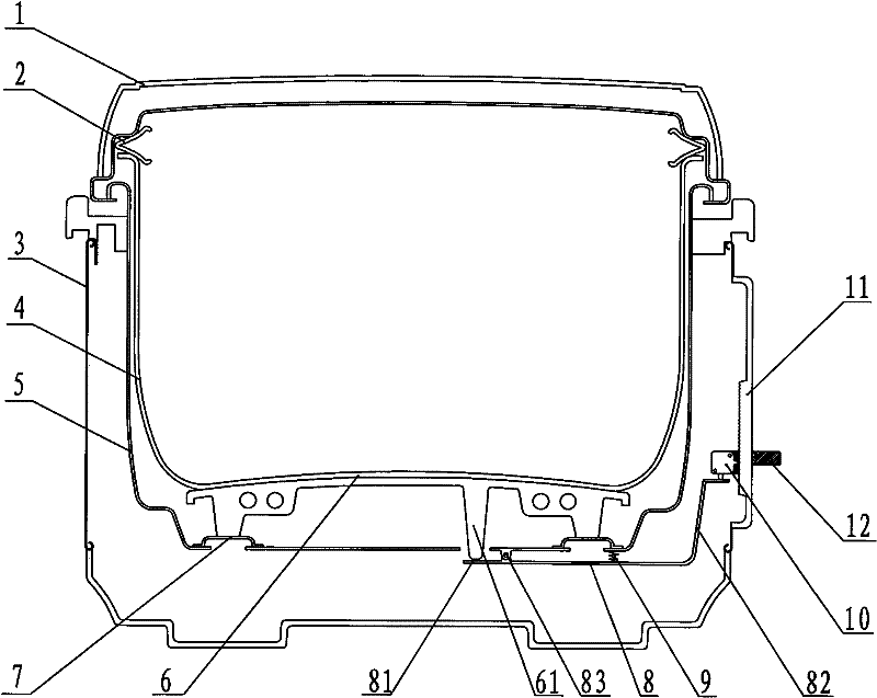
Figure 1 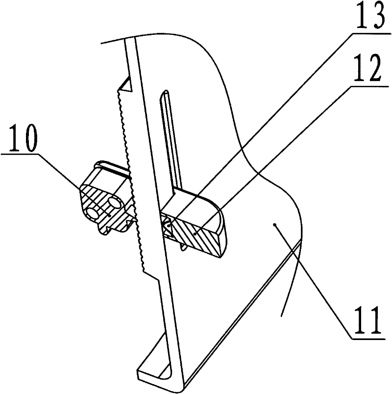
Figure 2 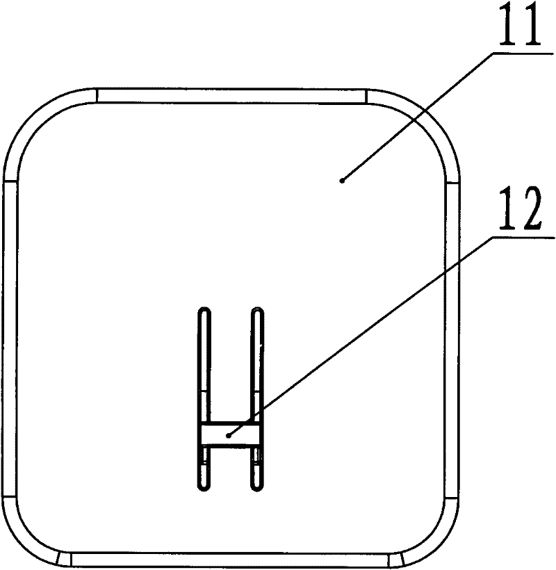
Figure 3
Abstract
Description
technical field
[0001] The invention relates to an electric pressure cooker, in particular to an electric pressure cooker capable of mechanically adjusting the inner pressure of the cooker. Background technique
[0002] Electric pressure cooker is an upgraded product of traditional pressure cooker and electric rice cooker. This product combines the characteristics and strengths of pressure cooker and electric rice cooker, and solves the dangerous factors existing in traditional pressure cooker. It has fast cooking, multi-purpose pot, energy saving and safety. Practical features. In order to fully ensure the safety of use in the electric pressure cooker, the pressure in the electric pressure cooker must be controlled so that the pressure in the electric pressure cooker does not exceed a certain dangerous value. At present, most people set an independent pressure control device with a micro switch or other alternative products on the bottom or below the outer pot to control t...
Examples
Embodiment 1
[0036] Such as figure 1 As shown, the electric pressure cooker includes a pot main body, a pot cover 1, and a sealing ring 2, and the pot main body includes an outer shell 3, an inner pot 4, an outer pot 5, a heater 6 and an electric control system; wherein the sealing ring 2 The outer pot 5 has an elastic bottom wall 7 and the heater 6 is supported on the bottom wall 7 of the outer pot 5 . On, the inner pot 4 is located above the heater 6 . The heater 6 is electrically connected with the electric control system. The lower part of the heater 6 is provided with a leg 61 and extends through the bottom wall 7 of the outer pot 5 to below the bottom wall 7 of the outer pot 5 .
[0037] A rigid lever 8 is provided in the space below the bottom wall 7 of the outer pot 5 , the lever 8 has a fixed fulcrum 83 , and the fulcrum 83 is arranged on the bottom wall 7 of the outer pot 5 . Wherein the length of the first end lever arm 81 before the fulcrum 83 is far less than the length of ...
Embodiment 2
[0045] Such as Figure 4As shown, the difference from Embodiment 1 is that the signal switch 10 is arranged on the lever arm 81 at the head end of the lever 8 and corresponds to the lower side of the leg 61 , and is arranged between the leg 61 There is a heat insulating pad 14 , and the lever arm 82 at the tail end of the lever 8 extends to the adjustment mechanism in an oblique direction and forms a transmission connection with it. The adjustment mechanism mainly includes an adjustment knob 121 and a pointer 15 . Such as Figure 5 As shown, the outer surface of the side wall 11 is provided with circularly arranged scale marks, and the adjustment knob 121 is provided with a pointer 15 . The adjusting knob 121 is rotatably fixed on the outer surface of the side wall 11 through the central shaft 16 . The adjusting knob 121 is provided with a drive arm 131, and the drive arm 131 pushes the tail end lever arm 82 of the lever 8 to move back and forth when turning, so that the lev...
Embodiment 3
[0049] Such as Figure 6 and Figure 7 As shown, different from the second embodiment, the way to drive the tail end lever arm 82 of the lever 8 can also be that a slideway is set on the side wall body 11 of the outer casing 3, and a slideway is set in the slideway. The adjustment arm 122 is provided with a slide block 132 inside the slideway, and the slide block 132 is connected with the adjustment arm 122 and is stuck on both sides of the side wall body 11 of the outer casing 3; The outside of block 132 is provided with a chute 17 from low to high and adapted to the tail end lever arm 82 of said lever 8, so that when said adjusting arm 122 is slid, said slide block 132 and its chute 17 also Along with the sliding, the tail end lever arm 82 of the lever 8 is forced to be depressed or lifted in the slide groove 17 , that is, the lever 8 rocks, thereby determining the position of the signal switch 10 . The position of the signal switch 10 is different, the pressure of the inn...