
Connecting structure for control panel and panel shell of gas stove
A connection structure and control panel technology, which is applied in the fields of gas heating water heaters and gas water heaters, can solve problems such as difficulty in improving the three-dimensional effect of gas appliances, and achieve the effects of reducing the risk of collision injuries, increasing strength, and enhancing the three-dimensional effect
Patent Information
- Authority / Receiving Office
- CN · China
- Current Assignee / Owner
- Publication Date
- 2012-08-01
Smart Images
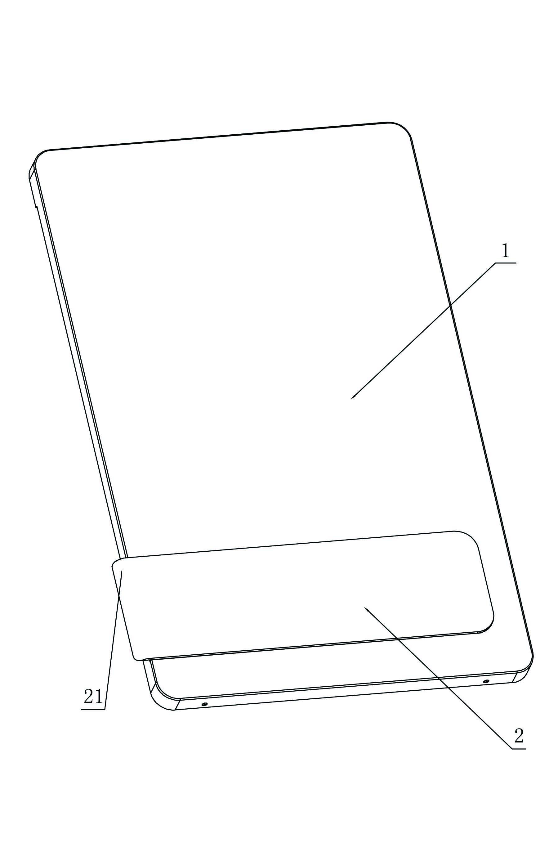
Figure 1 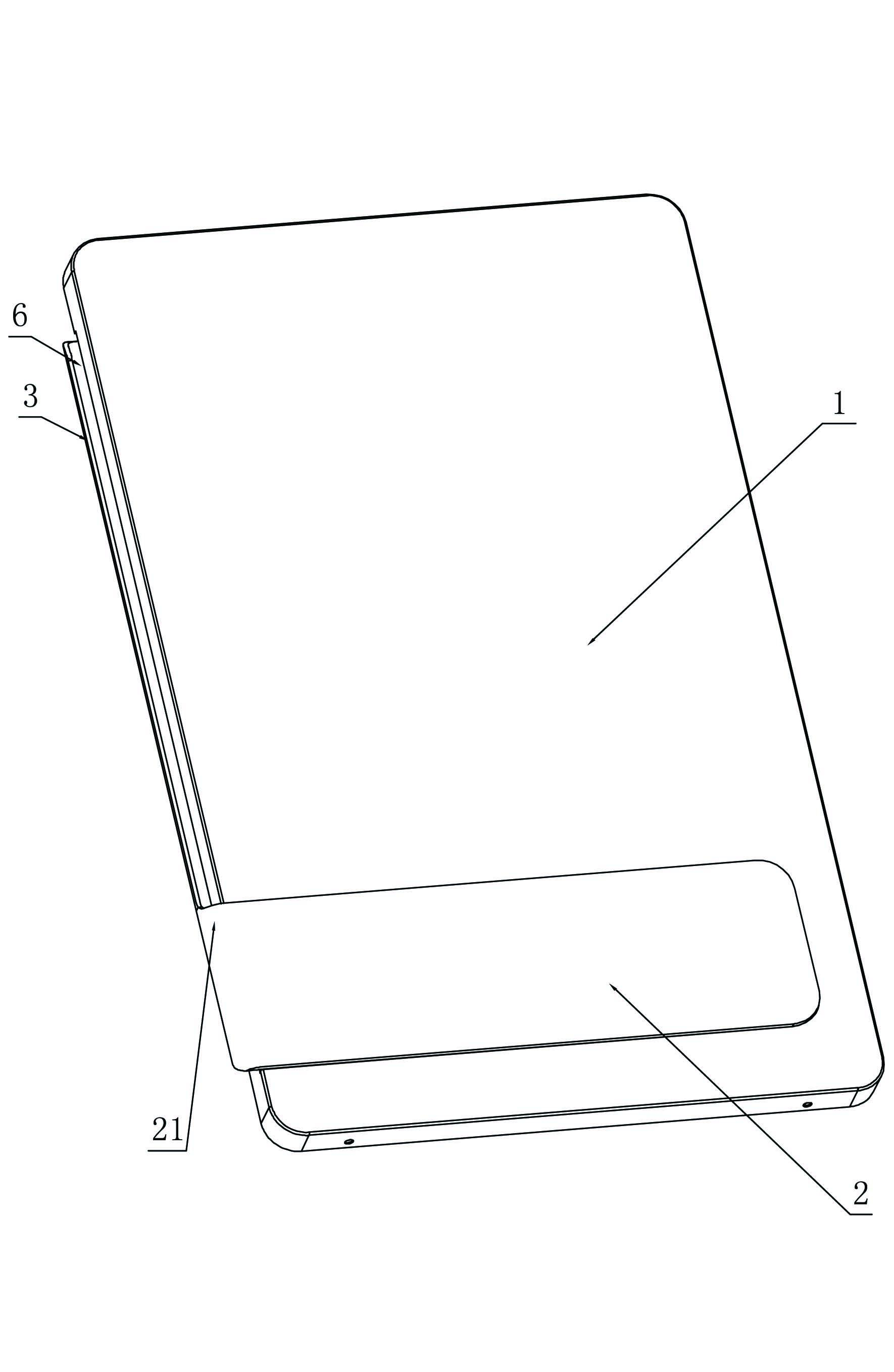
Figure 2 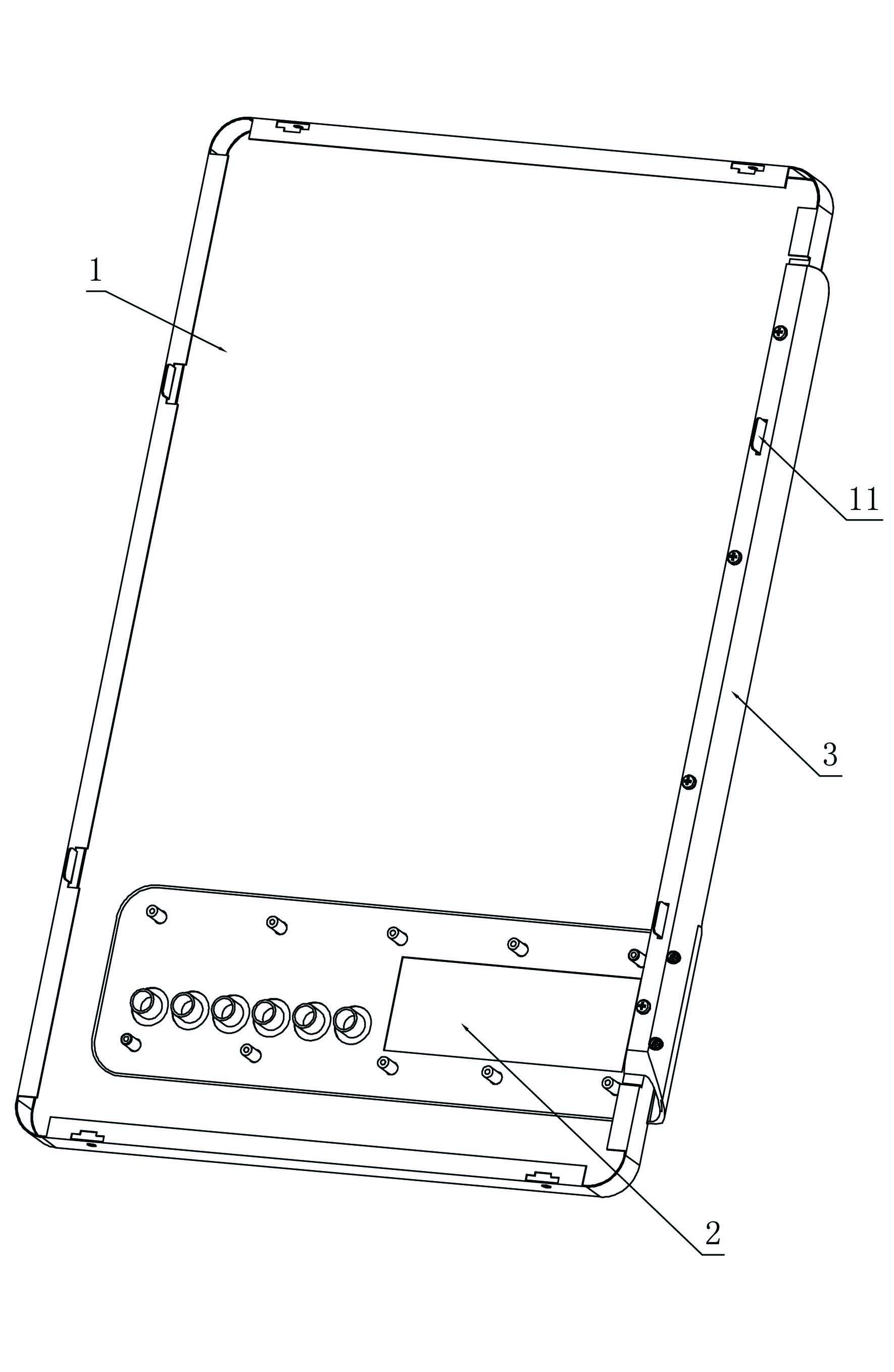
Figure 3
Abstract
Description
technical field
[0001] The invention relates to a connection structure between a control panel and a face shell of a gas appliance, and is especially suitable for gas water heaters, gas heating water heaters and the like. Background technique
[0002] In the prior art, the bodies of gas appliances such as domestic gas water heaters and gas heating water heaters are generally box-shaped, and the body is provided with a face shell and a display control panel, and the display control panel is installed on the face shell. When the body needs to be beautified and decorated, the following methods are usually used for decoration: 1. Decorate by changing the shape or pattern of the control panel; However, both of these two decoration methods are limited to the contour range of the face shell, and have a strong sense of plane, which makes it difficult to improve the three-dimensional sense of the gas appliance body. In order to overcome the above-mentioned defects, we have conducted...
Examples
specific Embodiment approach
[0025] Specific implementation methods: such as figure 1 As shown, this embodiment includes a face shell 1 and a control panel 2, the control plate 2 is arranged on the face shell 1, the control plate 2 is provided with a protrusion 21 extending to the outside of the outline of the face shell 1, and the protrusion 21 extends to the face shell 1 The exterior of the frontal profile.
[0026] Such as figure 2 , image 3 , Figure 4 and Figure 5 As shown, the face shell 1 is also provided with a support block 3 supporting the protruding portion 21, and the support block 3 is an L-shaped strip mainly composed of horizontal sides and vertical sides. The horizontal side of the support block 3 is connected to the face shell 1 , a separation groove 6 is formed between the vertical side and the face shell 1 , and one end of the vertical side supports the end of the protruding part 21 and smoothly transitions with the protruding part 21 . The support block 3 and the protruding par...