
Assembly type skin retractor
A modular, skin-based technology, applied in the field of surgical tools, can solve the problems of difficulty in grasping the pulling force, skin flap necrosis, and prolonged operation time, so as to reduce the burden on assistants, reduce the possibility, and ensure the effect of the operation.
Patent Information
- Authority / Receiving Office
- CN · China
- Patent Type
- Applications(China)
- Current Assignee / Owner
- Publication Date
- 2012-10-24
- Estimated Expiration
- Not applicable · inactive patent
Smart Images
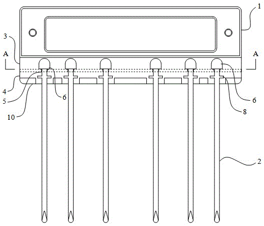
Figure 1 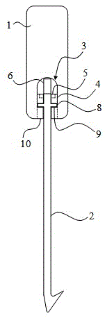
Figure 2 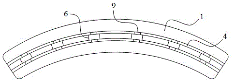
Figure 3
Abstract
Description
technical field
[0001] The invention relates to a surgical operation tool, in particular to a modular skin retractor for breast cancer skin flap free operation. Background technique
[0002] In surgical operations, the chief surgeon often has to be equipped with an assistant who is responsible for everting the skin or tissue near the incision, especially in breast cancer operations, where skin flaps are peeled off for sharp dissection, and the flap needs to be maintained at a certain tension to benefit the surgeon. For the operation, 2 to 3 assistants currently use towel forceps or vascular forceps to clamp the skin flap and then stretch it evenly and forcefully. Each assistant needs to pull 2 or more towel forceps or vascular forceps to complete the entire skin flap. The dissociation of the flap requires alternating between assistants to complete. However, it is best to complete the free flap operation continuously, otherwise the operation time will be prolonged. In add...
Examples
Embodiment Construction
[0014] The present invention will be further described below in conjunction with the accompanying drawings.
[0015] combine figure 1 , figure 2 , image 3 As shown, the assembled skin retractor of the present invention includes an arc-shaped handle 1 and several retractors 2 connected with the handle 1 . There is an opening in the middle of the handle 1 for easy grasping. The handle 1 is provided with a chute 3 from bottom to top on the lower surface. The two side walls of the chute 3 are provided with two arc-shaped positioning bars 4 along the direction of the arc surface. The positioning bar 4 The upper surface is provided with a plurality of bayonets 5 along the direction of the vertical arc-shaped positioning bar; the upper end of the draw hook 2 is provided with a positioning block 6 sliding on the positioning bar 4, and the two sides of the lower end of the positioning block 6 are provided with snap-fits in the bayonet 5. The positioning convex 7. The draw hook 2 ...