
Power-on resetting circuit
An electrical reset and discharge circuit technology, applied in electrical components, electronic switches, pulse technology, etc., can solve the problem that the capacitor discharges charge, affects the reliability and stability of the system, and the power-on reset circuit cannot correctly generate the power-on reset signal, etc. problem, to achieve the effect of accurate delay and low power consumption
Patent Information
- Authority / Receiving Office
- CN · China
- Current Assignee / Owner
- Publication Date
- 2013-01-23
Smart Images
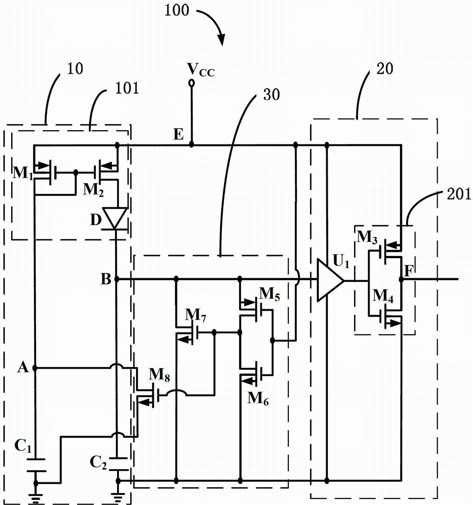
Figure 1 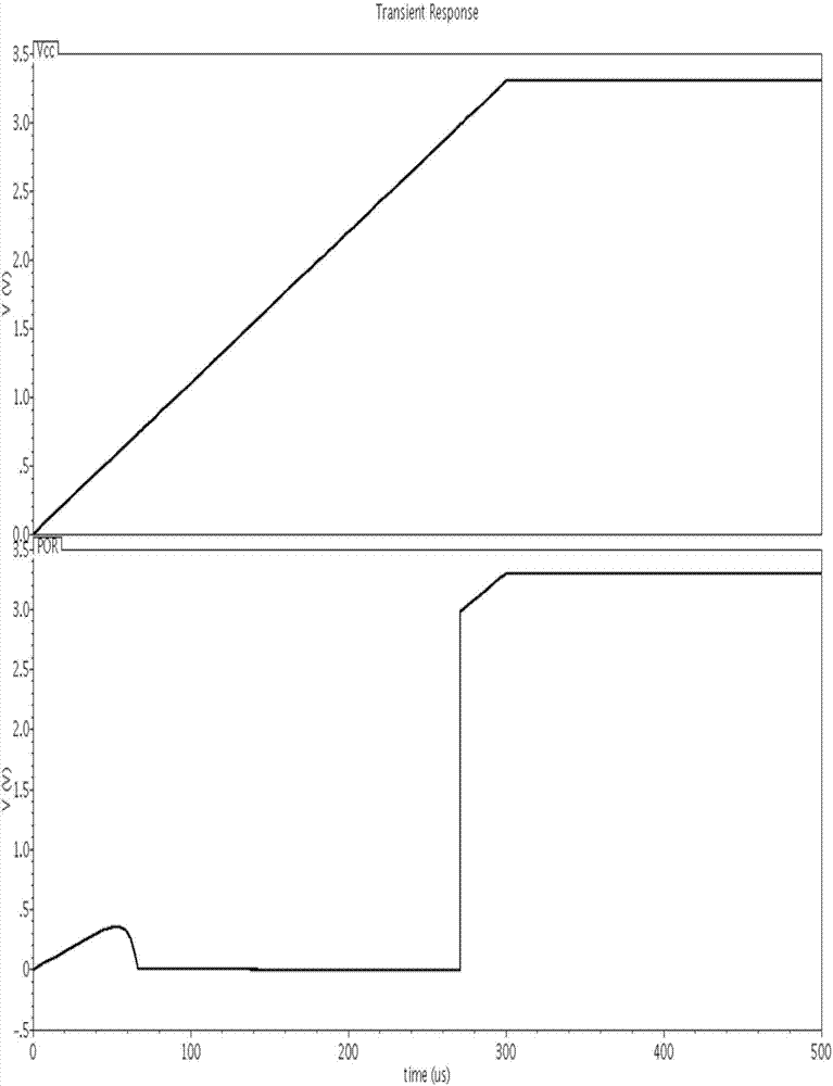
Figure 2 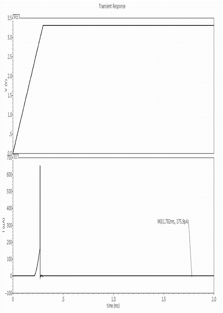
Figure 3
Abstract
Description
[0001] technical field
[0002] The invention relates to the field of integrated circuits, in particular to a power-on reset circuit.
[0003] Background technique
[0004] The power-on reset circuit has always been a necessary basic circuit module in the digital-analog hybrid and digital fields. When the digital circuit is powered on, in order to ensure the correct power-on logic sequence, it is necessary to keep the generated logic level in a certain state during the rise of the power supply voltage, and wait until the power supply voltage rises (that is, the process of power-on) to the specified value Then automatically jump to the working state and let the circuit start to work, so as to avoid the error state. The mainstream power-on reset current generally uses an RC delay circuit. After the power supply voltage rises to a specified value, a pulse signal with a certain pulse width is generated as a power-on reset signal. However, when the situation of rapid power-off...
Examples
Embodiment Construction
[0017] Below, in conjunction with accompanying drawing and specific embodiment, the present invention is described further:
[0018] like figure 1 Shown is the circuit diagram of the power-on reset circuit of the present invention. The power-on reset circuit 100 is used to generate a startup signal (or a reset signal) when the chip is powered on, so as to ensure that the chip is in a correct working state.
[0019] The power-on reset circuit 100 includes a power-on circuit 10 , a level trigger circuit 20 and a discharge circuit 30 . The power-on circuit 10 includes a current mirror 101, a first capacitor C1 and a second capacitor C2, and the current mirror 101 supplies power to the first capacitor C1 and the second capacitor C2 when the power-on reset circuit 100 is supplied with a power-on voltage Vcc. Charge. Specifically, the current mirror 101 includes a first MOS transistor M1 and a second MOS transistor M2, and the power-up circuit 10 further includes a diode D, the g...