
Filter circuit and radio terminal including filter circuit
A filter and circuit technology, which is applied in the field of radio terminals, can solve the problems of combining difficult bandpass filters with high-frequency integrated circuits, etc., and achieve the effects of expanding frequency range, steep attenuation characteristics, and increasing attenuation
Patent Information
- Authority / Receiving Office
- CN · China
- Patent Type
- Applications(China)
- Current Assignee / Owner
- Publication Date
- 2013-03-06
- Estimated Expiration
- Not applicable · inactive patent
Smart Images
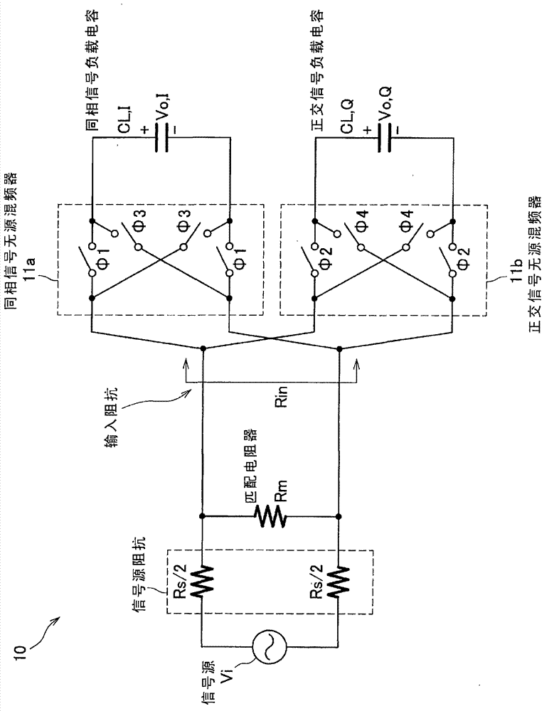
Figure 1 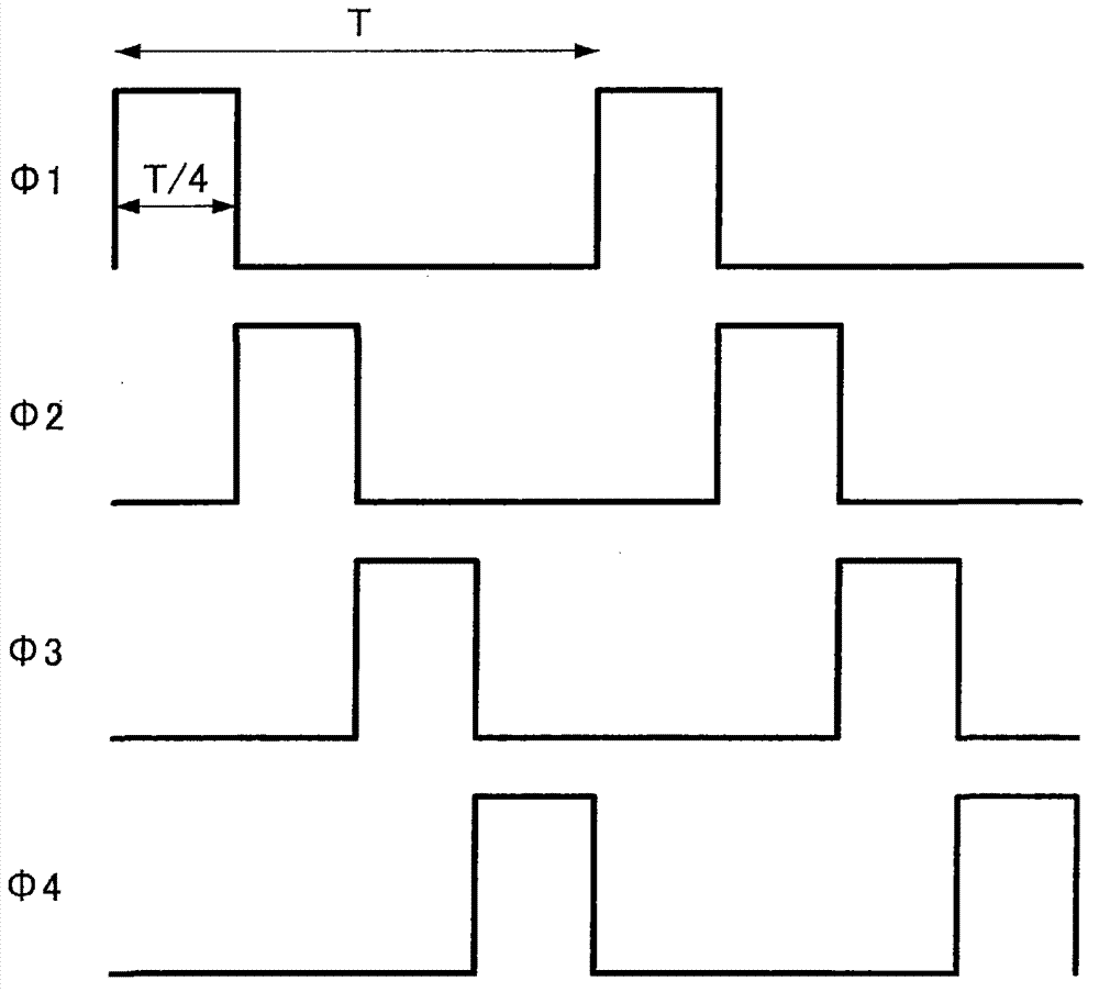
Figure 2 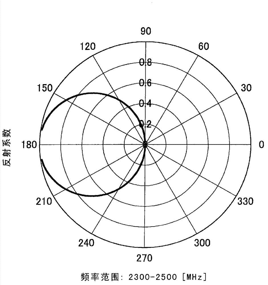
Figure 3
Abstract
Description
Technical field
[0001] The present invention relates to a filter circuit and a radio terminal including the filter circuit. Background technique
[0002] A mixer that converts the frequency of a high-frequency band signal and a band-pass filter that attenuates interference waves outside the high-frequency band are usually installed on a receiving front-end unit of a radio communication device. Since the band pass filter includes a surface acoustic wave filter and a dielectric resonator, it is difficult to incorporate the band pass filter into a high frequency integrated circuit. However, in recent years, attempts to integrate a frequency conversion filter circuit combining the two functions of a mixer and a bandpass filter into the front-end unit of the receiver have been reported, as shown in the following documents: BWCook , "Low-Power 2.4-GHz Transceiver With Passive RX Font-End and 400-mV Supply" by A. Berny, A. Molnar, S. Lanzisera and KSJPister, Journal of Solid State Circ...
Examples
no. 1 example
[0033] 3. The second embodiment of the present disclosure
[0034] 4. The third embodiment of the present disclosure
[0035] 5. Summary
[0036] 1. Related Technology
[0037] figure 1 It is a diagram illustrating a configuration example of a frequency conversion filter circuit according to the related art. figure 1 The frequency conversion filter circuit 10 shown in is rewritten in differential form in the following document Image 6 The circuit obtained by the quadrature mixer model disclosed in the document is BWCook, A. Berny, A. Molnar, S. Lanzisera and KSJPister’s "Low-Power 2.4-GHz Transceiver With Passive RX Font-End and 400-mV Supply", Journal of Solid State Circuits, Vol. 41, No. 12, pp. 2757-2766, Dec. 2006. In addition, "Low-Power 2.4-GHz Transceiver With Passive RX Font-End and 400-mV Supply" by BWCook, A. Berny, A. Molnar, S. Lanzisera and KSJPister, Journal of Solid State Circuits, Vol. 41, No. 12, pp. 2757-2766, in Dec. 2006 Image 6 The switch resistor Rsw of the p...