
Disc flow allocation radial variable high pressure plunger pump
A technology of high-pressure plunger pump and flow distribution, which is applied in variable capacity pump components, components of pumping devices for elastic fluids, pumps, etc., can solve the problems of limited processing conditions, irreparable, complex structures, etc., and achieve Reduced manufacturing cost, repairability, ease of use, and improved volumetric efficiency
Patent Information
- Authority / Receiving Office
- CN · China
- Patent Type
- Applications(China)
- Current Assignee / Owner
- Publication Date
- 2013-03-13
- Estimated Expiration
- Not applicable · inactive patent
Smart Images
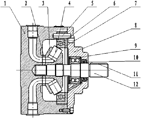
Figure 1 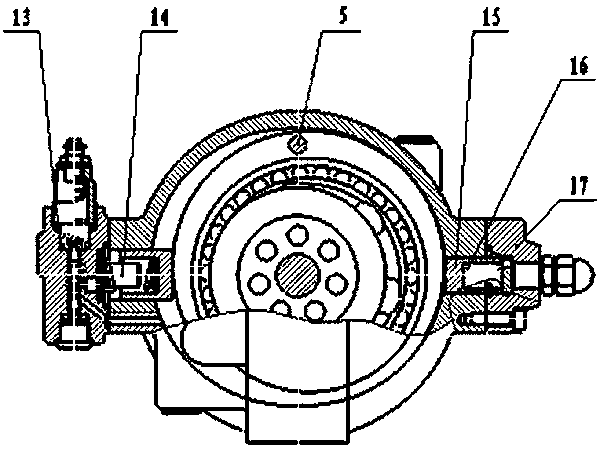
Figure 2 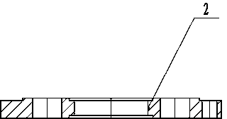
Figure 3
Abstract
Description
technical field
[0001] The invention belongs to the field of power components of hydraulic transmission, and relates to a radially variable high-pressure plunger pump with disk flow distribution. Background technique
[0002] At present, traditional radial piston pumps at home and abroad mostly use two oil distribution methods—valve distribution or shaft distribution. The structure is complex and difficult to process, especially the distribution shaft, which is limited by processing conditions and difficult to popularize. Due to its irreparability after wear, the product appears to be more expensive in general use. Contents of the invention
[0003] The problem to be solved by the present invention is to overcome the deficiencies of the prior art and provide a disc flow radial variable high-pressure plunger pump. The oil distribution disc can be made of alloy steel, which has strong wear resistance and has Certain repairability, the processing is basically conventional ma...
Examples
Embodiment Construction
[0017] The specific implementation, structure, features and effects provided by the present invention will be described in detail below in conjunction with the accompanying drawings and preferred embodiments.
[0018] Such as Figure 1~4 A radial variable high-pressure plunger pump with plate flow distribution shown includes a pump body, a pump cover, a rotor, a stator and a plunger. The oil distribution plate 2 is a circular oil distribution plate. The oil window 18, the static pressure support sealing belt 19 and the silencer groove 20, the oil distribution plate, the pump body 1 and the rotor 3 are combined to form an oil passage. When in use, these three parts are closely connected to generate oil flow and boost pressure. The plunger holes on the rotor are radially arranged, the flow distribution surface of the rotor is closely attached to the flow distribution plate, and the plunger holes are set to form an angle with the axis of the transmission shaft 12, which makes the...