
Hydraulic motor dragging system used for load of high-power and wide speed adjusting range
A technology of hydraulic motor and drag system, which is applied in the directions of fluid pressure actuation system components, servo motors, fluid pressure actuation devices, etc., can solve the problems of limited technical effect and complex structure.
Patent Information
- Authority / Receiving Office
- CN · China
- Current Assignee / Owner
- Publication Date
- 2013-06-26
Smart Images
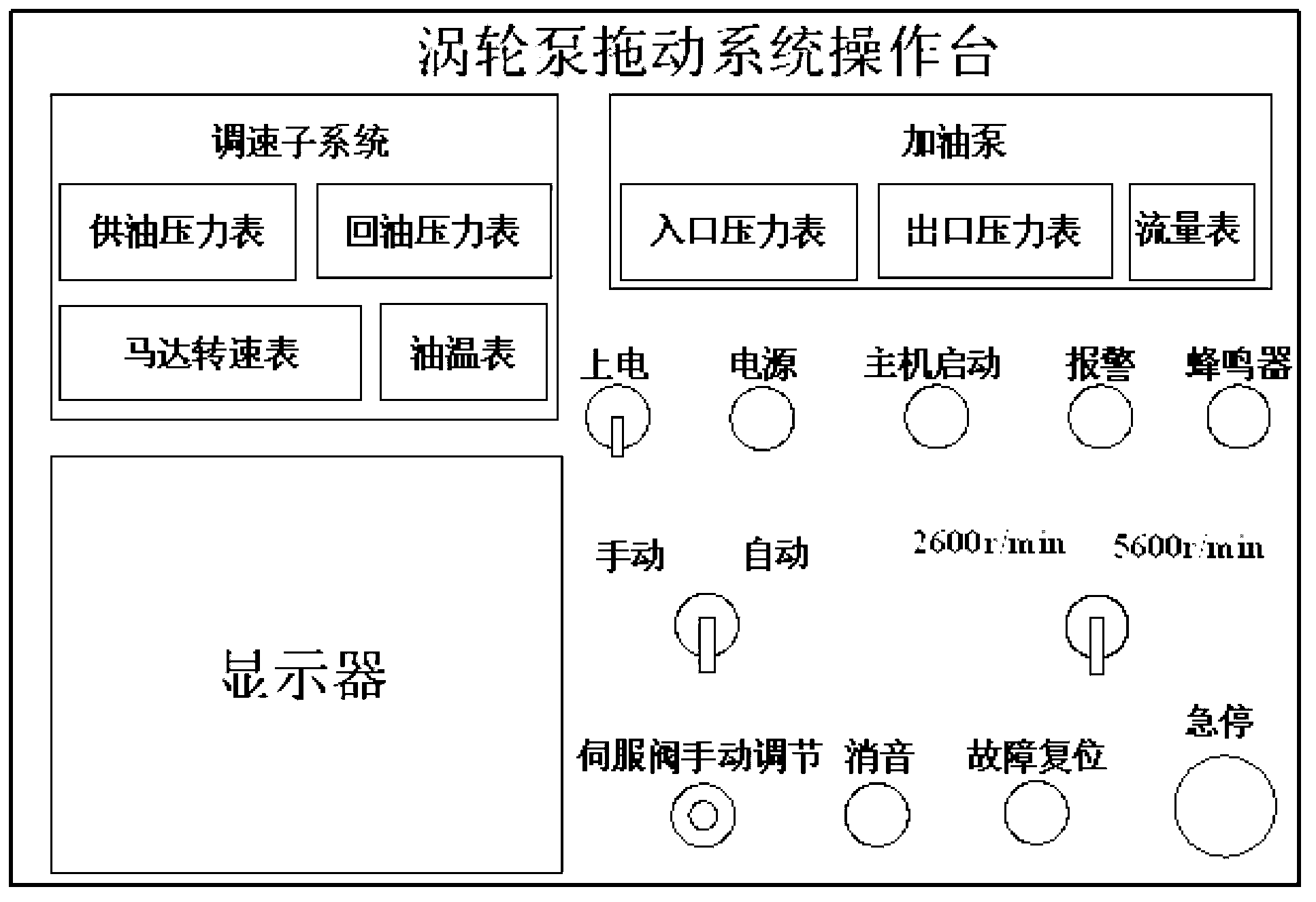
Figure 1 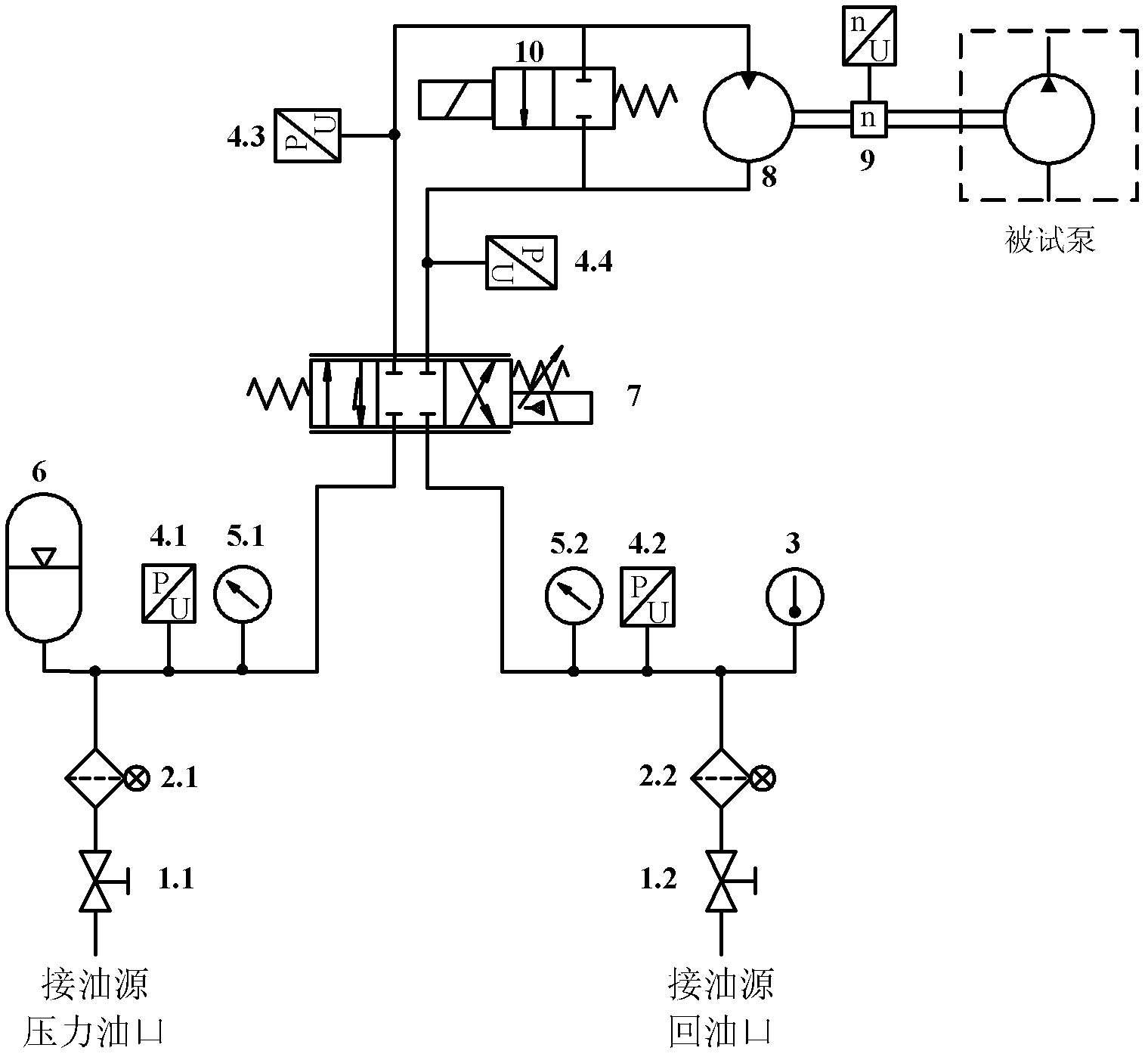
Figure 2 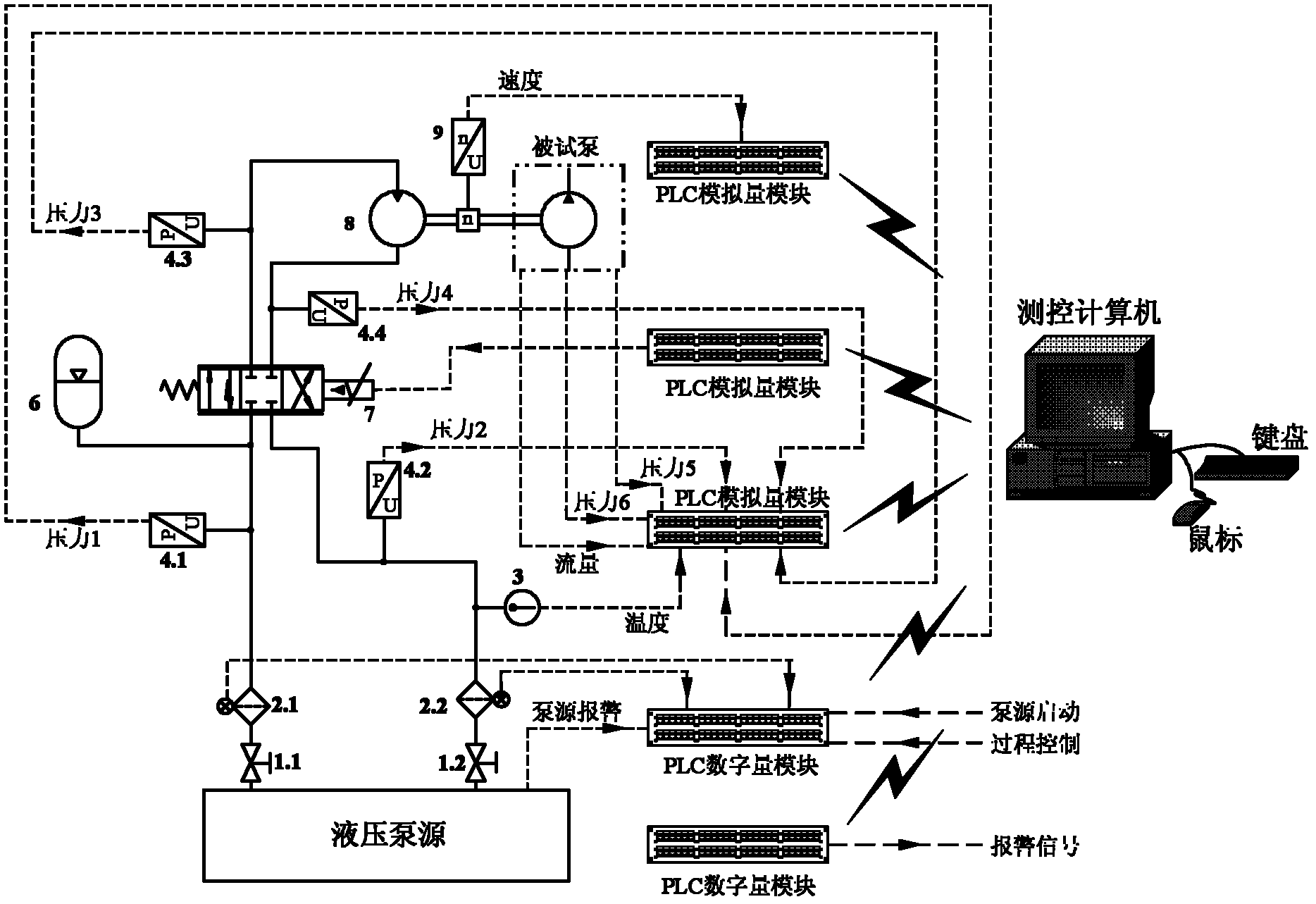
Figure 3
Abstract
Description
Technical field:
[0001] The invention relates to the technical field of structural design and application of hydraulic and electrical control systems, and in particular provides a hydraulic motor drive system for loads with high power and wide speed regulation range. Background technique:
[0002] In the prior art, the structure of the hydraulic motor driving system is relatively complicated, and the technical effect is relatively limited. Therefore, people expect to obtain a hydraulic motor drive system for loads with high power and wide speed regulation range with good technical effect. Invention content:
[0003] The object of the present invention is to provide a hydraulic motor drive system for loads with high power and wide speed regulation range with good technical effect.
[0004] The invention provides a hydraulic motor drive system for loads with high power and wide speed regulation range, which is installed on a hydraulic pump; the feature is that the hydraulic...
Examples
Embodiment 1
[0105] A hydraulic motor drive system for loads with high power and wide speed regulation range, which is installed on a hydraulic pump; the hydraulic motor drive system is specifically composed of the following two parts: a hydraulic system and an electrical system; wherein: hydraulic The system consists of the following parts: high pressure ball valve 1.1, low pressure ball valve 1.2, high pressure oil filter with alarm 2.1, low pressure oil return filter with alarm 2.2, temperature sensor 3, pressure sensor A4.1, pressure sensor B4.2, Pressure sensor C4.3, pressure sensor D4.4, high pressure gauge 5.1, low pressure gauge 5.2, accumulator 6, servo valve 7, hydraulic motor 8, speed sensor 9, bypass valve 10; where:
[0106] Pressure ball valve 1.1 and low-pressure ball valve 1.2 are respectively connected to the pressure oil port and oil return port of the oil source, high-pressure oil filter 2.1 with alarm is connected to pressure ball valve 1.1, and the following parts are c...