
Evaporator and liquid reservoir used for loop heat pipe and application thereof
A loop heat pipe and evaporator technology, which is applied to indirect heat exchangers, heat exchanger sealing devices, heat exchange equipment, etc., can solve problems such as unstable operation and reduced start-up performance of loop heat pipes, and achieve simple design and manufacture. Improve start-up performance, operational stability and reliability, and reduce heat leakage
Patent Information
- Authority / Receiving Office
- CN · China
- Patent Type
- Applications(China)
- Current Assignee / Owner
- Publication Date
- 2013-10-09
- Estimated Expiration
- Not applicable · inactive patent
Smart Images
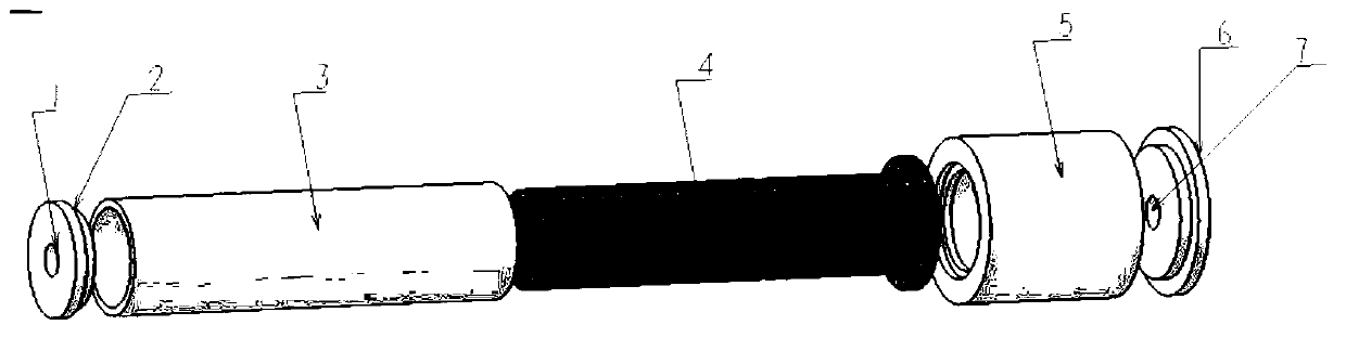
Figure 1 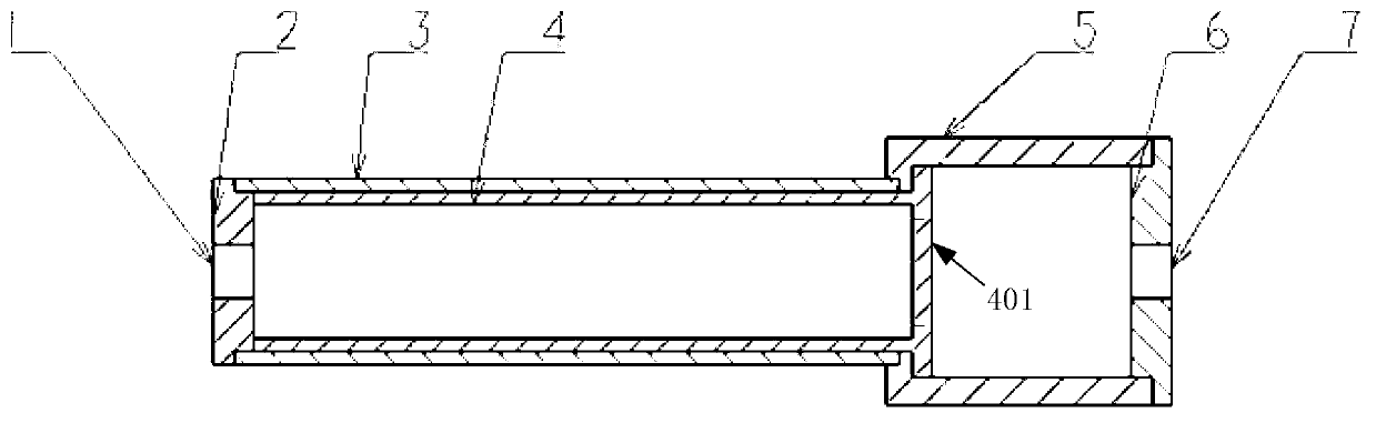
Figure 2
Abstract
Description
technical field
[0001] The invention relates to the technical field of evaporators, in particular to an evaporator and a liquid storage device for a loop heat pipe and applications thereof. Background technique
[0002] The loop heat pipe is a high-efficiency two-phase heat transfer device, which uses the evaporation and condensation of the working fluid to transfer heat, and the circulation of the working fluid is driven by the capillary pressure generated by the capillary core of the evaporator without external power. Compared with other heat transfer equipment, the loop heat pipe has outstanding advantages such as large heat transfer, long transfer distance, high temperature control accuracy, strong anti-gravity capability, compact structure, convenient installation, and autonomous operation. And the cooling of electronic components and other fields have broad application prospects.
[0003] For the cylindrical evaporator loop heat pipe, which was developed earlier and h...
Examples
Embodiment Construction
[0017] The evaporator and liquid reservoir for a loop heat pipe provided by the present invention and their application will be described in detail below with reference to the drawings and embodiments.
[0018] The invention provides an evaporator and a liquid reservoir for a loop heat pipe, such as figure 1 with figure 2 As shown, both the evaporator and the liquid receiver are in the shape of circular tubes, and both are coaxial. The evaporator includes an evaporator end cover 2 and an evaporator housing 3, and the accumulator includes an accumulator housing 5 and an accumulator end cap 6, and the evaporator and the accumulator are separated by a capillary wick 4 .
[0019] Between the evaporator end cover 2 and the evaporator housing 3 , between the evaporator housing 3 and the liquid storage housing 5 , and between the liquid storage housing 5 and the liquid storage end cover 6 are all connected by welding.
[0020] The evaporator and liquid receiver form a loop with t...