
Uniform-section blade-type microscale turbine electric spark machining device and process method thereof
A processing device and EDM technology, applied in positioning devices, metal processing equipment, metal processing machinery parts, etc., can solve the problems of low machining accuracy and large deformation of micro-scale turbine blades, reduce the difficulty of design and manufacturing, and reduce the processing time. The effect of deforming and simplifying the motion track
Patent Information
- Authority / Receiving Office
- CN · China
- Patent Type
- Applications(China)
- Current Assignee / Owner
- Publication Date
- 2013-12-25
- Estimated Expiration
- Not applicable · inactive patent
Smart Images
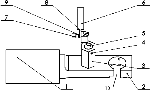
Figure 1 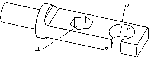
Figure 2 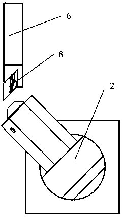
Figure 3
Abstract
Description
technical field
[0001] The invention relates to a constant-section airfoil microscale turbine electric discharge machining device and a process method thereof, which belong to the field of microscale turbine machining. Background technique
[0002] Micro-scale turbines will be widely used in various industries such as industry, agriculture, environmental protection, medical and health care, etc., and are key components in micro-power devices such as micro-engines and micro-pumps. The successful development of this miniature, portable power device will not only have a huge impact on the MEMS industry, but also on the industries based on modern microelectronics, information and biotechnology.
[0003] Micro-scale turbines are generally difficult-to-machine materials with high hardness, so the primary problem of micro-scale turbine machining is whether it can be processed, and secondly, how to accurately, stably and efficiently process turbine blades and other profiles with com...
Examples
Embodiment Construction
[0033] Please refer to figure 1 As shown, a constant-section airfoil micro-scale turbine electric discharge machining device includes a clamping rod 6, an integrated positioning plate 2, an indexing prism 3 and a reference base 1, and the electrode 8 is installed on the clamping rod with screws 7 and nuts 9. On the rod 6, after adjusting the position, clamp it, and then connect the clamping rod 6 to the spindle of the machine tool; position the workpiece 5 on the indexing prism 3, and lock it with the locking screw 4 to make the two become a rigid body. The degree prism 3 is positioned and clamped on the integrated positioning plate 2; finally, the integrated positioning plate 2 is installed on the reference base 1, rotated to adjust the angle and then locked.
[0034] Please refer to figure 1 and figure 2 As shown, the integrated positioning plate 2 is a positioning plate for processing the electrode 8 and the workpiece 5, and the regular hexagonal hole 11 for positioning ...