
Control method for optimizing thyristor controlled transformer type controllable electric reactor
A technology of thyristor control and transformer type, applied in harmonic reduction devices, AC networks to reduce harmonics/ripples, reactive power adjustment/elimination/compensation, etc., can solve the problem of increasing investment, increasing floor area, and current Distortion and other issues
Patent Information
- Authority / Receiving Office
- CN · China
- Patent Type
- Applications(China)
- Current Assignee / Owner
- Publication Date
- 2014-03-26
Smart Images
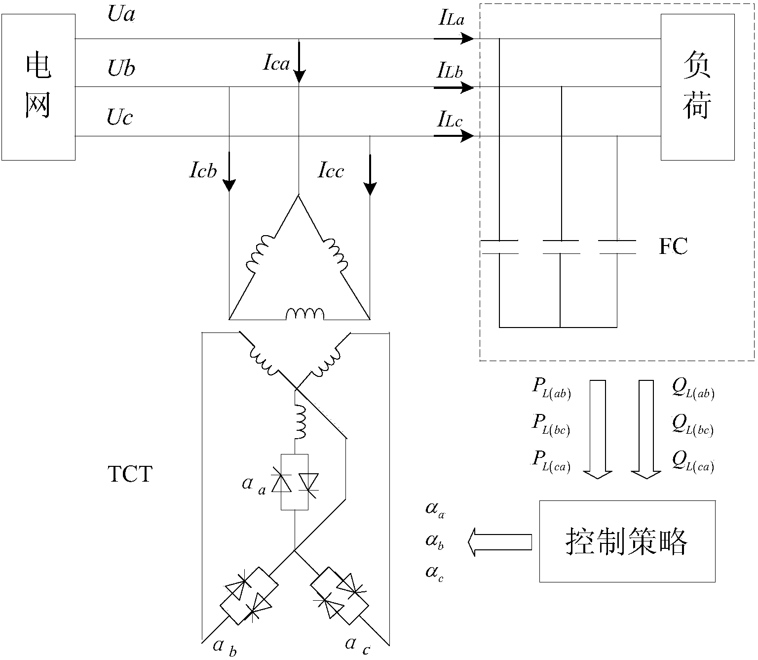
Figure 1 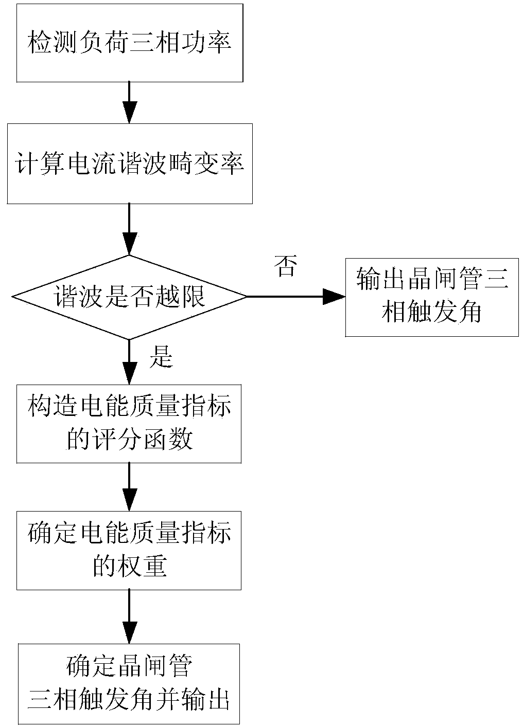
Figure 2 
Figure 3
Abstract
Description
technical field
[0001] The invention belongs to the field of reactive power compensation in electric power systems, and relates to an optimal control method for a thyristor-controlled transformer-type controllable reactor. Background technique
[0002] In recent years, with the continuous development of the national economy, asynchronous motors and power electronic devices have begun to be connected to the power grid in large quantities. These loads need to absorb a large amount of reactive power to work normally, which will increase the active power loss of the power system, reduce the utilization rate of equipment, and affect The power transmission capacity has a negative impact on the safety and stability of the power system operation. At the same time, with the increase of asymmetric loads such as electric arc furnaces and electric locomotives in the power system, the problem of three-phase imbalance in the power grid has attracted more and more attention. The three-phas...
Examples
Embodiment Construction
[0040] The technical solutions of the present invention will be specifically introduced below in conjunction with the accompanying drawings.
[0041] A thyristor-controlled transformer-type controllable reactor optimization control method of the present invention, the main wiring of the system figure 1 shown, where U a , U b , U c is the grid phase voltage, I ca , I cb , I cc is the three-phase current flowing into the reactor, I La , I Lb , I Lc is the load three-phase current, P L(ab) ,P L(bc) ,P L(ca) , Q L(ab) , Q L(bc) , Q L(ca) is the three-phase power of the load. The control flow chart of the present invention is as figure 2 shown, including the following steps:
[0042] 1) Detect the load three-phase power P when the controllable reactor is not connected L(ab) ,P L(bc) ,P L(ca) , Q L(ab) , Q L(bc) , Q L(ca) .
[0043] 2) Calculate the harmonic distortion rate of the three-phase current, the specific process is:
[0044] 21) Use the load three-...