
Groove buffer of hydraulic cylinder
A hydraulic cylinder and buffer technology, applied in the field of hydraulic cylinder buffers, can solve the problems of large hydraulic impact and poor buffering effect, and achieve the effect of small hydraulic impact, simple structure and stable operation
Patent Information
- Authority / Receiving Office
- CN · China
- Current Assignee / Owner
- Publication Date
- 2014-06-11
- Estimated Expiration
- Not applicable · inactive patent
Smart Images
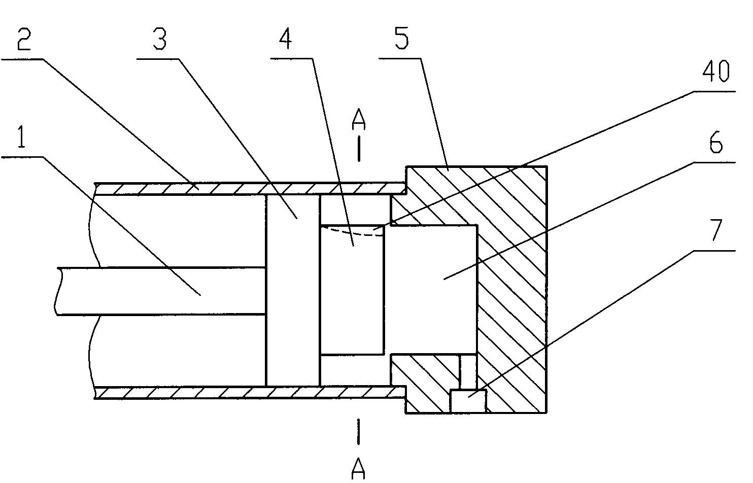
Figure 1 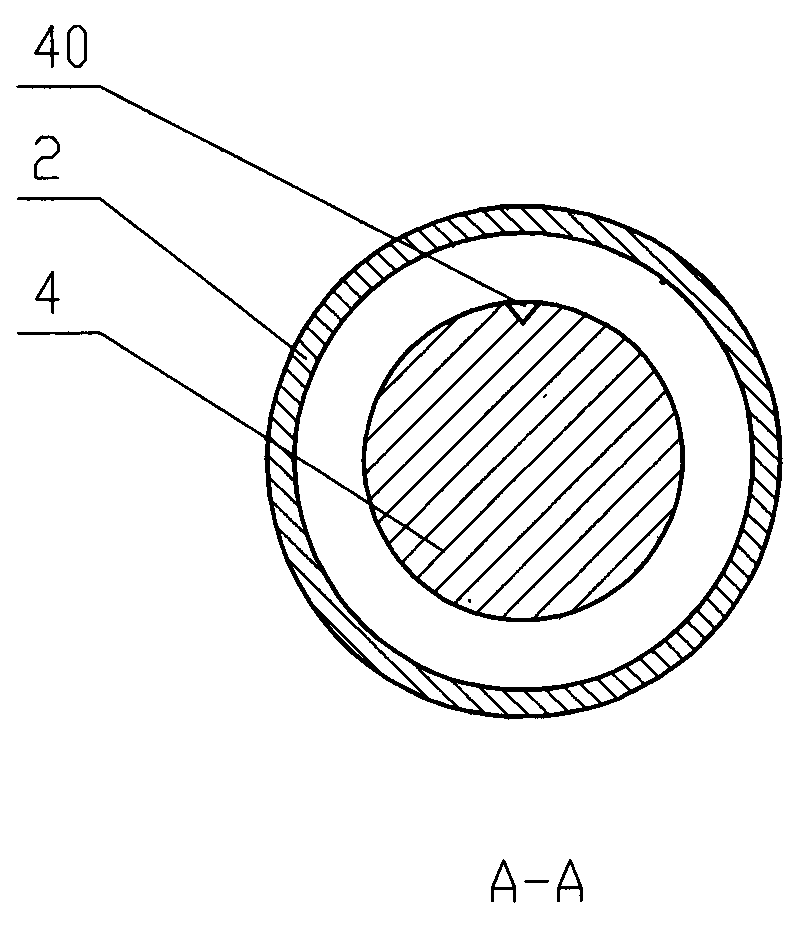
Figure 2
Abstract
Description
technical field
[0001] The invention relates to the field of hydraulic equipment, in particular to a buffer of a hydraulic cylinder. Background technique
[0002] When the hydraulic cylinder moves at high speed to the end of the stroke, severe mechanical collisions often occur. In addition, the sudden stop of the piston often causes water hammer in the pipeline, resulting in great impact and noise. The above mechanical shocks not only affect the working performance of mechanical equipment, but also damage hydraulic cylinders and other components of the hydraulic system, which is very dangerous. In order to prevent or reduce this kind of impact vibration, a buffer device is installed inside the hydraulic cylinder, which can play a buffering role to a certain extent. Generally, the buffer device used is an annular throttling buffer. The disadvantages of the traditional annular throttling buffer are poor buffering effect and large hydraulic shock. Contents of the invention ...
Examples
Embodiment Construction
[0009] See figure 1 , figure 2 , the present invention comprises a hydraulic cylinder 2, a piston 3 and a cylinder cover 5 fixedly connected to the hydraulic cylinder 2, the piston 3 is fixedly connected to the plunger 1, the cylinder cover 5 has a cylindrical cavity 6 and an orifice 7, and the orifice 7 and the The cavity 6 is connected, the piston 3 is fixedly connected to the cylindrical buffer block 4, the outer diameter of the cylindrical buffer block 4 is slightly smaller than the inner diameter of the cavity 6, and the outer wall of the buffer block 4 has an arc-shaped groove 40 with a triangular cross section. The depth gradually increases towards the end of the buffer block 4 .
[0010] When the present invention works, when the plunger 1 moves toward the cylinder head 5 with the piston 3, after the buffer block 4 enters the cylindrical cavity 5, a buffer oil cavity is formed between the cavity 5 and the piston 3, and the sealed oil only It can flow out of the groo...