
Reactive power compensation control method, device and system
A compensation control and power system technology, applied in reactive power compensation, reactive power adjustment/elimination/compensation, etc., can solve problems such as slow dynamic switching, achieve fast reactive power compensation, solve slow dynamic switching, and ensure stability Effect
Patent Information
- Authority / Receiving Office
- CN · China
- Patent Type
- Patents(China)
- Current Assignee / Owner
- Publication Date
- 2016-12-07
Smart Images
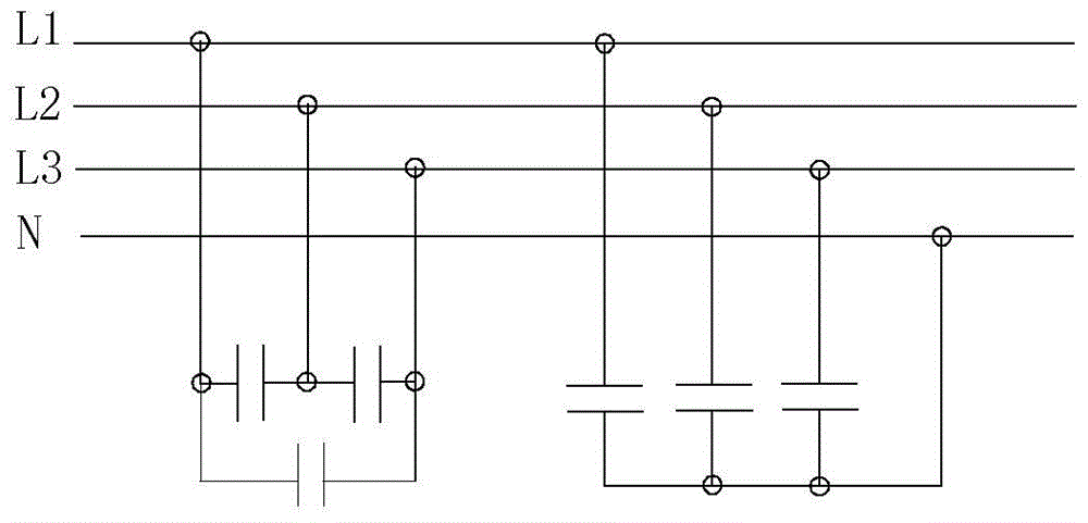
Figure 1 
Figure 2 
Figure 3
Abstract
Description
technical field
[0001] The present invention relates to the field of power system control, in particular to a reactive power compensation control method, device and system. Background technique
[0002] Such as figure 1 As shown, the current reactive power compensation is mainly realized through phase separation, joint compensation or separate blend compensation. figure 1 In the compensation method shown, the power distribution cabinets used for reactive power compensation are all under centralized control, and the switching of capacitors is also compensated in a centralized way. Because of the centralized control, the total power factor of the system can also be improved, but The response speed of switching capacitors is slow, but it can’t do anything about the rapid changes of the impact load. During the fast “run-stop” period of the load, the capacitors cannot be switched normally, because it cannot be compensated quickly, so the reactive power consumption of such loads ...
Examples
Embodiment Construction
[0024] First of all, some nouns or terms appearing in the process of describing the embodiments of the present invention are applicable to the following explanations:
[0025] In order to enable those skilled in the art to better understand the solutions of the present invention, the following will clearly and completely describe the technical solutions in the embodiments of the present invention in conjunction with the drawings in the embodiments of the present invention. Obviously, the described embodiments are only It is an embodiment of a part of the present invention, but not all embodiments. Based on the embodiments of the present invention, all other embodiments obtained by persons of ordinary skill in the art without making creative efforts shall fall within the protection scope of the present invention.
[0026] It should be noted that the terms "first" and "second" in the description and claims of the present invention and the above drawings are used to distinguish s...