
LED dispensing and packaging device with position sensor and alarm
A technology for encapsulating equipment and sensors, which is applied to devices and coatings that coat liquid on the surface, and can solve problems such as adverse effects on processing accuracy and large overall impact on the workbench
Patent Information
- Authority / Receiving Office
- CN · China
- Current Assignee / Owner
- Publication Date
- 2015-03-04
Smart Images
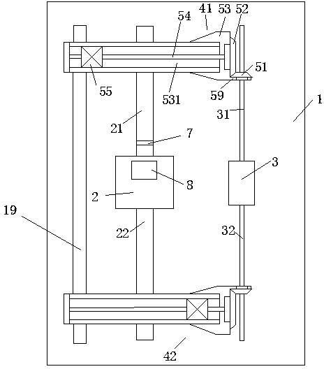
Figure 1 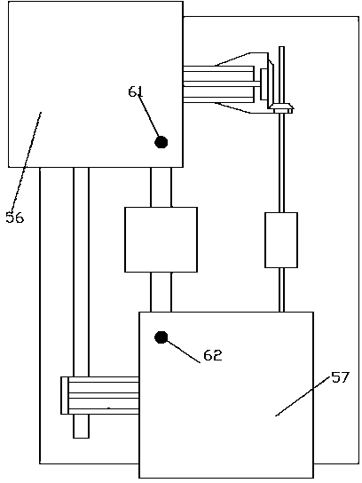
Figure 2
Abstract
Description
technical field
[0001] The invention relates to the technical field of LED encapsulation, in particular to an LED dispensing encapsulation device with a position sensor and an alarm. Background technique
[0002] LED packaging usually adopts the method of dispensing glue. When dispensing glue, use the LED board to move horizontally and vertically, and the dispensing head is fixed, so as to realize the relative movement between the dispensing head and the LED board, so as to dispens glue at different positions of the LED board.
[0003] However, when the weight of the LED board is large, due to the fast moving speed, it has a large impact on the workbench as a whole, thus adversely affecting the processing accuracy. Contents of the invention
[0004] The purpose of the present invention is to provide an LED dispensing packaging method, which can reduce the impact on the workbench during packaging, thereby improving the processing accuracy.
[0005] According to an aspect ...
Examples
Embodiment Construction
[0014] Attached below Figure 1-2 , the present invention will be described in detail.
[0015] An LED dispensing packaging device with a position sensor and an alarm, comprising a frame 1, a front slide assembly 42, a rear slide assembly 41, a longitudinal drive motor 2 and a transverse drive motor 3, wherein the frame 1 A frame guide rail 19 is arranged longitudinally on the upper frame, and the rear slide assembly 41 and the front slide assembly 42 are separately arranged on the frame 1 and are slidably fitted with the frame guide rail 19; Both the drive motor 2 and the transverse drive motor 3 are fixedly arranged on the frame 1 between the rear slide assembly 41 and the front slide assembly 42;
[0016] The front end of the longitudinal drive motor 2 is connected to the front longitudinal drive screw 22, the rear end is connected to the rear longitudinal drive screw 21, and the rear longitudinal drive screw 21 is connected to the wire on the rear slide assembly 41. The ...