

Positive pacing pulse generation circuit applied to cardiac pacemaker
A cardiac pacemaker and circuit generation technology, applied in the direction of electric pulse generator circuit, etc., can solve the problems of many peripheral devices, increase the design complexity and production cost, and achieve the reduction of occupied resources, reduce the burden and design difficulty, The effect of low energy consumption
Patent Information
- Authority / Receiving Office
- CN · China
- Patent Type
- Applications(China)
- Current Assignee / Owner
- Publication Date
- 2015-05-20
Smart Images
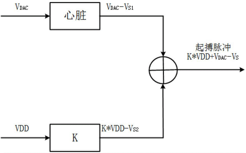
Figure 1 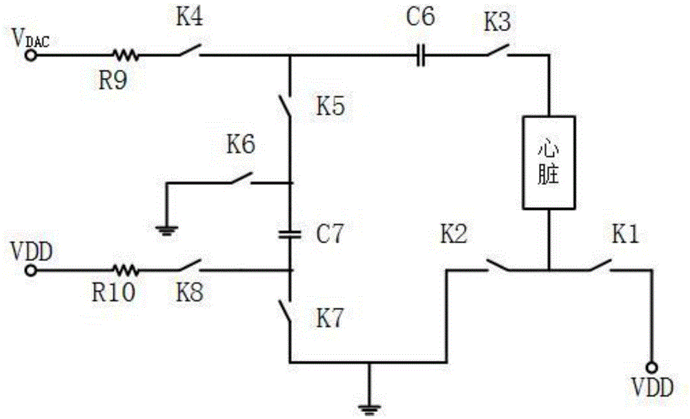
Figure 2 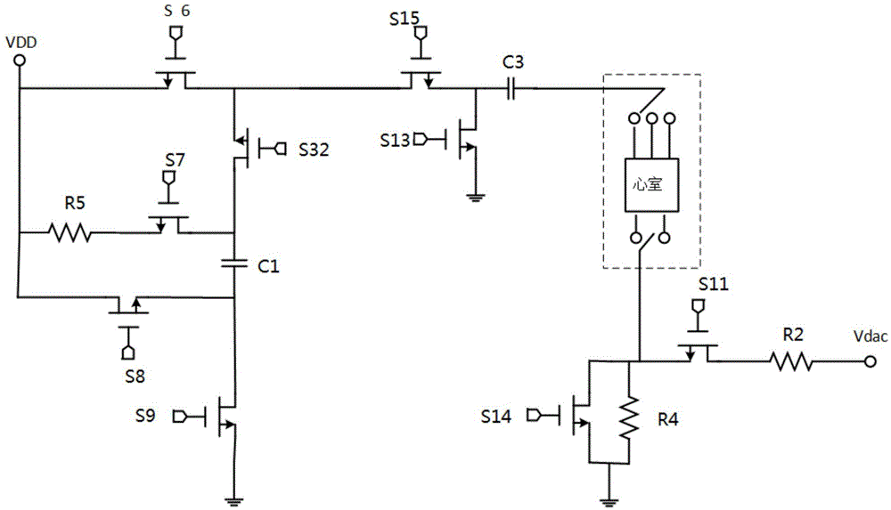
Figure 3
Abstract
Description
technical field
[0001] The invention belongs to the technical field of integrated circuits, and in particular relates to a positive pacing pulse generating circuit applied to a cardiac pacemaker. Background technique
[0002] With the improvement of people's health concepts and the rapid development of medical conditions, integrated circuit technology combined with biomedicine is more and more widely used, and cardiac pacemakers are a typical example. Among them, the pacing pulse generation circuit is the core circuit in various cardiac pacemakers (single-chamber monopolar, dual-chamber monopolar, and dual-chamber bipolar). The cardiac stimulation signal can be automatically adjusted with multiple levels of stimulation cycle, stimulation pulse width and stimulation amplitude according to the situation. With the increasing popularity of cardiac pacemakers, efficient and integrated pacing pulse generation circuits are essential.
[0003] Pacing pulses in a cardiac pacemaker ...
Examples
Embodiment Construction
[0021] The present invention will be described in further detail below in conjunction with the accompanying drawings.
[0022] see image 3 and 4 , the present invention includes a sixth MOS transistor S6, the source end of the sixth MOS transistor S6 is connected to the power supply VDD, the gate end is connected to an external drive circuit, and the drain end is connected to the drain end of the fifteenth MOS transistor S15 and the drain end of the thirty-second MOS transistor S32. The source terminals are connected; the gate terminal of the fifteenth MOS transistor S15 is connected to the external drive circuit, the source terminal is connected to the negative terminal of the third capacitor C3 and the drain terminal of the thirteenth MOS transistor S13, and the positive terminal of the third capacitor C3 is connected to the ventricle input terminal, the source terminal of the thirteenth MOS transistor S13 is grounded, and the gate terminal is connected to an external driv...