
Ultraviolet detector optical subdivision device
An ultraviolet detector and optical technology, applied in the field of ultraviolet detectors, can solve the problems of inability to maintain the instrument on site, high processing requirements, unfavorable convenience, etc., and achieve the effects of correcting the motor rotation angle, reducing production costs, and optimizing operations
Patent Information
- Authority / Receiving Office
- CN · China
- Current Assignee / Owner
- Publication Date
- 2015-07-15
Smart Images
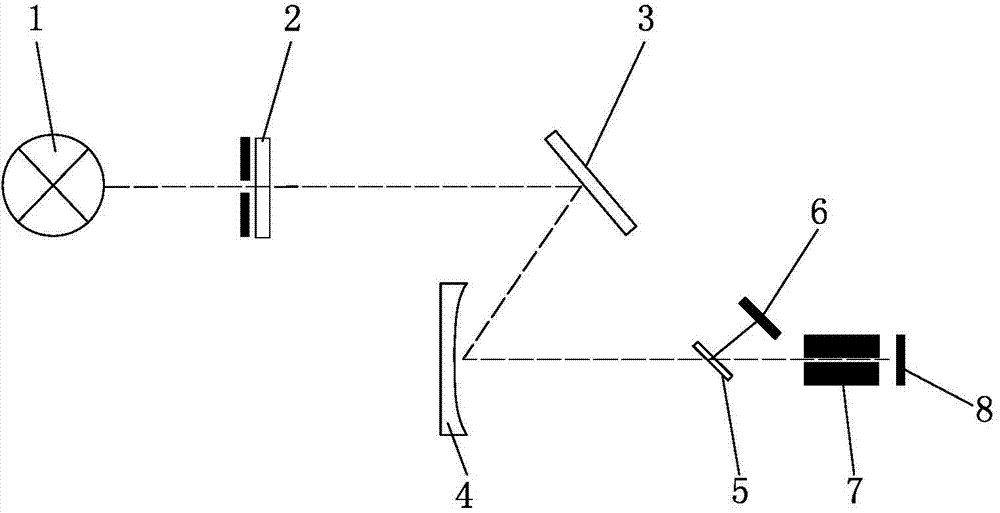
Figure 1 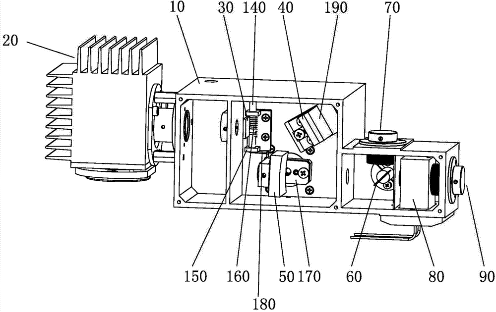
Figure 2 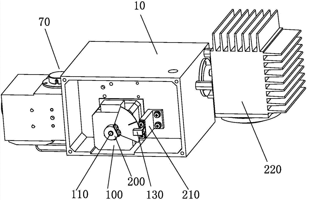
Figure 3
Abstract
Description
Technical field:
[0001] The invention belongs to the technical field of ultraviolet detectors, in particular to an optical subdivision device of ultraviolet detectors. Background technique:
[0002] In a traditional liquid chromatography instrument, a UV detector is generally equipped, including: a light source 1, a filter mirror 2, a mirror 3, a concave grating 4, a half-mirror 5, a reference photocell 6, and a flow-through cell 7 And sample photocell 8. It measures the change of the sample concentration by quickly recording the change of the absorbance of the mobile phase at a specific wavelength, so the optical unit is the core component of the instrument (see figure 1 ). Generally, the wavelength range required by chromatographic instruments is 200nm to 700nm, and the rotation angle of the grating is less than 30 degrees. Therefore, the traditional optical unit uses the mechanical structure of a sinusoidal screw to subdivide the rotation angle of the grating, and conve...
Examples
Embodiment Construction
[0023] The present invention will be further described below with specific embodiment, see figure 2 —4:
[0024] An ultraviolet detector optical subdivision device, including a light source 20, a filter 30, a mirror 40, a concave grating 50, a half mirror 60, a reference photocell 70, a flow Through the pool 80 and the sample photocell 90, the light of the lamp source 20 passes through the optical filter mirror 30, the mirror 40, the concave grating 50, the half mirror 60 successively, and passes through the reference photocell 70 and the half mirror 60 respectively from the half mirror 60. Flow through pool 80, sample photocell 90, described grooved grating 80 is driven to rotate by stepper motor 100, is provided with the optocoupler stopper 120 that rotates synchronously with grooved grating 80 on the motor shaft 110, on the optocoupler stopper One side of 120 is provided with an optocoupler 130 that cooperates with the optocoupler block 120 , and each time the power is tu...