
Manufacturing process and equipment for nickel-chromium-molybdenum alloy cast iron composite roller in forged steel roller neck
A nickel-chromium-molybdenum alloy and composite roll technology is applied in the manufacture of composite rolls in the steel rolling industry, and in the field of nickel-chromium-molybdenum alloy cast iron composite roll technology and equipment. Achieve the effect of overcoming tissue segregation, high density and uniform tissue
Patent Information
- Authority / Receiving Office
- CN · China
- Patent Type
- Applications(China)
- Current Assignee / Owner
- Publication Date
- 2016-02-17
Smart Images
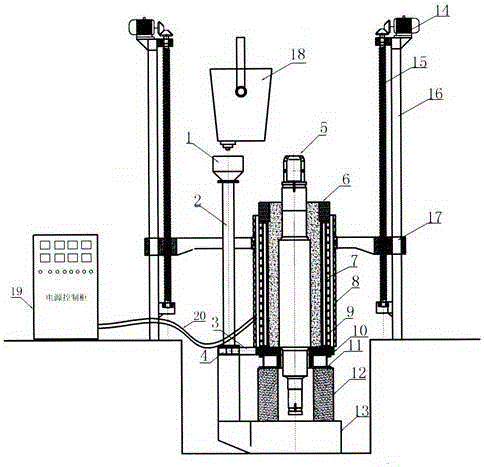
Figure 1 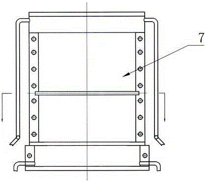
Figure 2 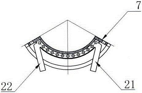
Figure 3
Abstract
Description
technical field
[0001] The invention belongs to the technical field of metal pressure processing, and in particular relates to a process and equipment for a nickel-chromium-molybdenum alloy cast iron composite roll in a forged steel roll neck, which is suitable for manufacturing composite rolls in the steel rolling industry. Background technique
[0002] The roll is known as the "mother of steel". It is a tool for plastically deforming metal materials in the rolling production of steel, aluminum, copper and other metals. Rolling is an indispensable key component and the most important bulk consumption component, and its consumption cost is about 5% to 15% of the steel rolling production cost. If factors such as production downtime, reduced production and increased equipment maintenance due to roll consumption are considered, the proportion of production costs will be even higher.
[0003] Rolling mill is an important equipment in metal pressure processing and production, an...
Examples
Embodiment 1
[0060] Embodiment 1: in figure 1 , figure 2 , image 3 , Figure 4 , Figure 5 , Figure 6 Among them, the equipment has a gantry-type regional directional solidification lifting device 16, a lifting platform 17 is installed on the gantry-type regional directional solidification lifting device 6, an electromagnetic induction heater 8 is installed on the lifting platform 17, and the lifting motor 14 rotates and lifts The screw 15 or hydraulic equipment drives the lifting table 17 to move up and down at the set speed, and the electromagnetic induction power control cabinet 19 is installed on the side of the directional solidification lifting equipment 16 in the gantry type area. The two output ends of the electromagnetic induction power control cabinet 19 are cooled by water. The cable 20 is connected to the two ends of the electromagnetic induction heater 8, and there is a base bracket at the bottom of the directional solidification lifting device 16 in the gantry type are...
Embodiment 2
[0076] Example 2: In figure 1 , figure 2 , image 3 , Figure 4 , Figure 5 , Figure 6Among them, the equipment has a gantry-type regional directional solidification lifting device 16, a lifting platform 17 is installed on the gantry-type regional directional solidification lifting device 6, an electromagnetic induction heater 8 is installed on the lifting platform 17, and the lifting motor 14 rotates and lifts The screw 15 or hydraulic equipment drives the lifting table 17 to move up and down at the set speed, and the electromagnetic induction power control cabinet 19 is installed on the side of the directional solidification lifting equipment 16 in the gantry type area. The two output ends of the electromagnetic induction power control cabinet 19 are cooled by water. The cable 20 is connected to the two ends of the electromagnetic induction heater 8, and there is a base bracket at the bottom of the directional solidification lifting device 16 in the gantry type area, a...
Embodiment 3
[0092] Example 3: In figure 1 , figure 2 , image 3 , Figure 4 , Figure 5 Among them, the equipment has a gantry-type regional directional solidification lifting device 16, a lifting platform 17 is installed on the gantry-type regional directional solidification lifting device 6, an electromagnetic induction heater 8 is installed on the lifting platform 17, and the lifting motor 14 rotates and lifts The screw 15 or hydraulic equipment drives the lifting table 17 to move up and down at the set speed, and the electromagnetic induction power control cabinet 19 is installed on the side of the directional solidification lifting equipment 16 in the gantry type area. The two output ends of the electromagnetic induction power control cabinet 19 are cooled by water. The cable 20 is connected to the two ends of the electromagnetic induction heater 8, and there is a base bracket at the bottom of the directional solidification lifting device 16 in the gantry type area, and a support...