
Calculation Method of Absolute Speed of Train
A technology of absolute speed and calculation method, applied in the field of rail transit, can solve problems such as high cost and inability to determine the direction of target movement
Patent Information
- Authority / Receiving Office
- CN · China
- Patent Type
- Patents(China)
- Current Assignee / Owner
- Publication Date
- 2019-02-22
Smart Images
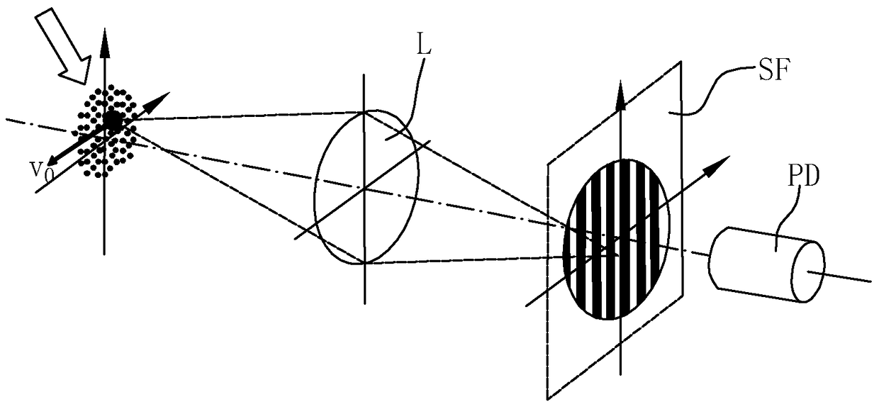
Figure 1 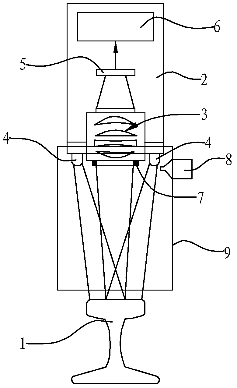
Figure 2 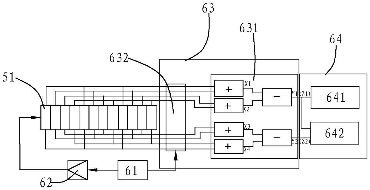
Figure 3
Abstract
Description
technical field
[0001] The invention relates to the technical field of rail transit, in particular to a train absolute speed measurement device, and also to a train speed calculation method. Background technique
[0002] The driving speed is an important input of the train control system, and the accurate measurement of the speed plays a vital role in ensuring the driving safety. At present, the sensors used to detect the speed of trains are mainly divided into two categories: rotational speed sensors and line speed sensors. The speed sensor includes magnetoelectric sensor, Hall sensor and photoelectric sensor, etc. The speed sensor measures the speed of the motor, gearbox or axle and converts the speed into the running speed of the train. This type of sensor has high accuracy and reliability for the rotational speed, but cannot accurately measure the train speed when the wheels are spinning and slipping. The line speed sensor includes GPS sensor, track circuit sensor and ...
Examples
Embodiment 1
[0065] like figure 2 and image 3 As shown, the train absolute speed measuring device in this embodiment is installed on the train near the upper position of the track 1, and the absolute speed of the train relative to the ground is calculated by collecting image information of the track 1.
[0066] The train absolute speed measuring device includes a substrate 2 , an optical lens 3 , a light source 4 , a linear array CCD 51 and a signal processing unit 6 .
[0067] The optical lens 3 is arranged on the base body 2 and is located directly above the track 1. The optical lens 3 can be composed of convex lenses, concave lenses, etc. according to the required optical processing requirements. In order to avoid condensation on the surface of the optical lens 3 in a cold environment, a heating assembly 7 for heating the optical lens 3 is also provided below the optical lens 3 .
[0068] In order to avoid contamination of the optical lens 3 by dust and oil stains, a purge assembly ...
Embodiment 2
[0102] The difference between the present embodiment and the first embodiment is only that the speed direction of the train is identified by the identification method of the D flip-flop;
[0103] like Figure 6 As shown, the method for the D flip-flop to identify the speed direction of the train is specifically: in the direction calculation module 642, the signals Z1 and Z2 are respectively processed by low-pass filtering and high-pass filtering to obtain two sinusoidal signals V1 and V1 with a phase difference of 90°. The sinusoidal signal V2, the sinusoidal signal V1 and the sinusoidal signal V2 are respectively processed by the Schmitt trigger to obtain two square wave signals S1 and square wave signal S2 with a phase difference of 90°, and the square wave signal S1 is input to the D flip-flop Input the square wave signal S2 to the D terminal of the D flip-flop, and the output signal Q of the D flip-flop represents the direction signal; the sine signal V1,
[0104] like ...
Embodiment 3
[0109] The difference between this embodiment and Embodiment 1 is only that an acceleration sensor is installed on the train, the direction of the acceleration sensor is set to be the same as the positive direction of the train, and the acceleration data of the train is collected using the acceleration sensor;
[0110] like Figure 9 As shown, in the direction calculation module 642, the absolute speed of the train is calculated to obtain derivative data; when the absolute speed of the train is 0, no direction judgment is required; when the sign of the acceleration data is consistent with the sign of the derivative data, the train is judged Forward travel; when the sign of the acceleration data is inconsistent with the sign of the derivative data, it is judged that the train is traveling in the reverse direction.
[0111] Using the acceleration sensor method to identify the speed direction of the train, the algorithm is simple and the cost is low. In order to ensure accurate ...