
A Dual-row Two-Dimensional Time Grating Linear Displacement Sensor
A linear displacement, dual-row technology, applied in the direction of instruments, measuring devices, electrical devices, etc., can solve the problems of difficult manufacturing, multi-layered, complex sensor structure, etc., to reduce the number of layers of coils and the complexity of winding The effect of eliminating the influence of high-order harmonics and simplifying the structure of the sensor
Patent Information
- Authority / Receiving Office
- CN · China
- Patent Type
- Patents(China)
- Current Assignee / Owner
- Publication Date
- 2018-11-13
Smart Images
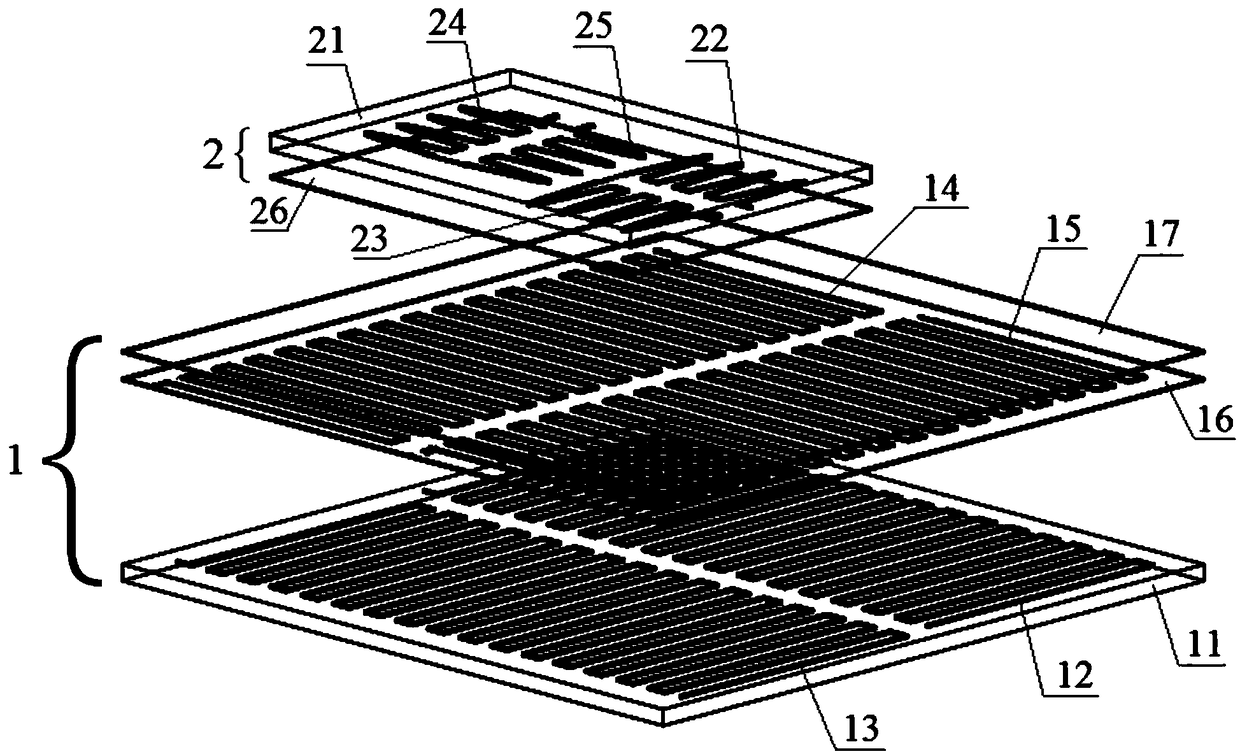
Figure 1 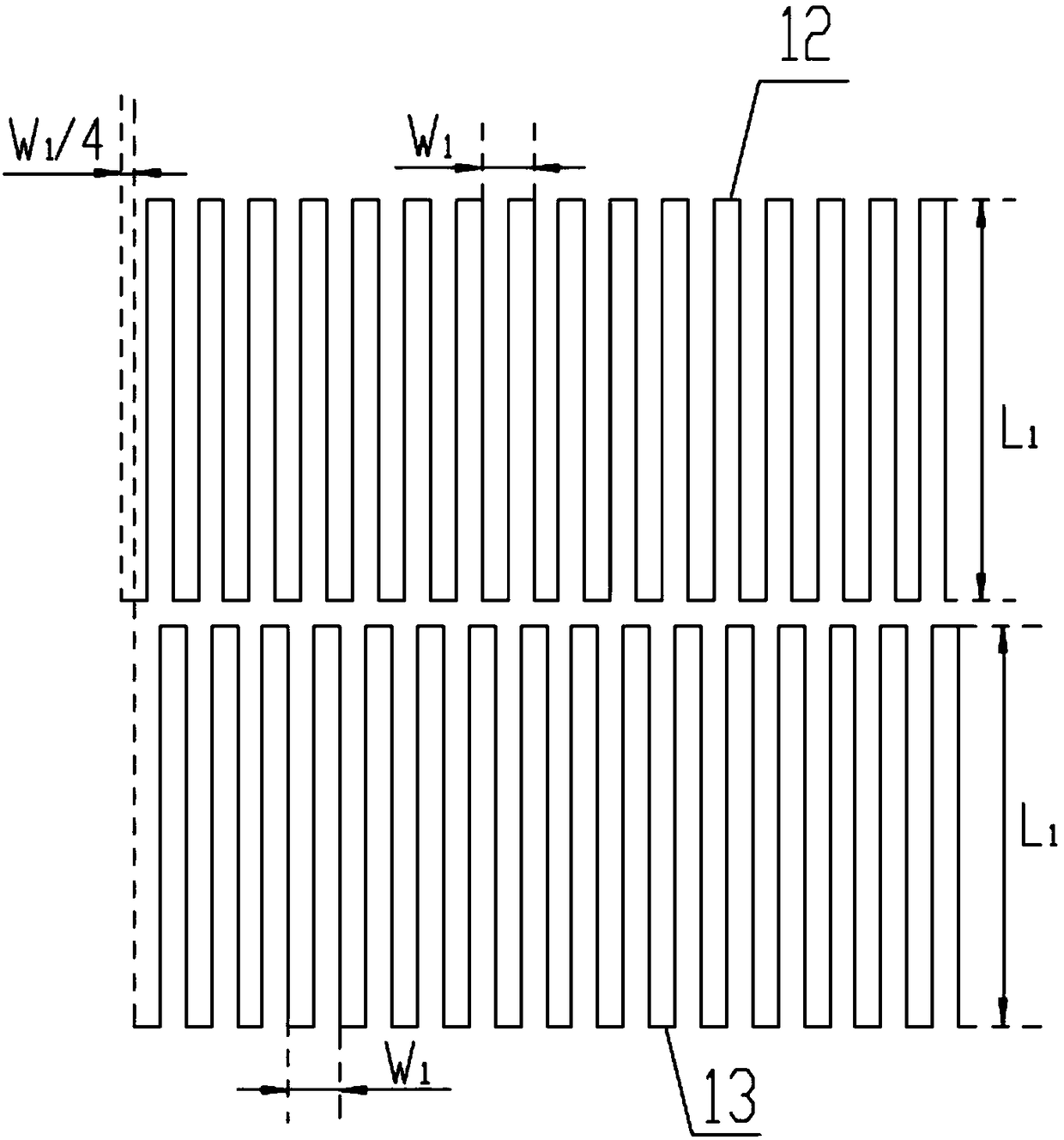
Figure 2 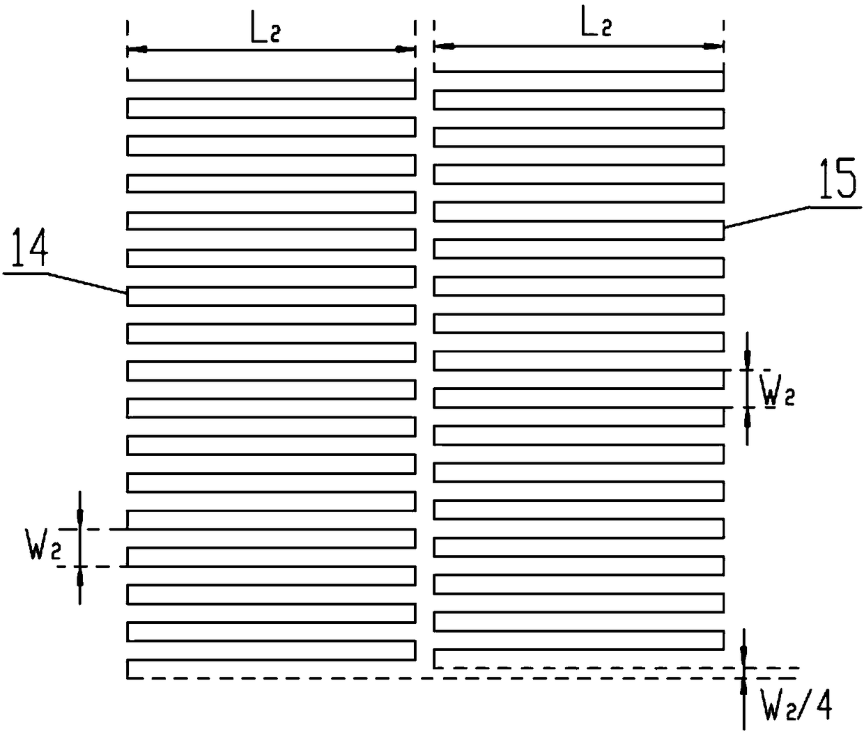
Figure 3
Abstract
Description
technical field
[0001] The invention belongs to the technical field of precision measurement sensors, and in particular relates to a dual-row two-dimensional time grating linear displacement sensor. Background technique
[0002] Linear displacement measurement is the most basic geometric quantity measurement, and it exists in a large number in industrial and scientific practices represented by manufacturing. There are two types of existing sensors for plane two-dimensional displacement measurement. One is to install two linear displacement sensors vertically with a relative difference of 90° on the plane to obtain the plane two-dimensional linear displacement respectively. The other is to use a single two-dimensional displacement sensor. The two-dimensional linear displacement sensor acquires displacements in two dimensions respectively. Installing two linear displacement sensors vertically will bring Abbe error and installation positioning error to the measurement, and som...
Examples
Embodiment Construction
[0017] The present invention will be described in detail below in conjunction with the accompanying drawings.
[0018] Such as Figure 1 to Figure 5 The dual-row two-dimensional time grating linear displacement sensor shown includes a fixed scale 1 and a moving scale 2 parallel to the fixed scale 1 with a gap of 0.2 mm.
[0019] The scale 1 includes a scale matrix 11, a first excitation coil 12 and a second excitation coil 13 arranged in the first wiring layer on the side of the scale matrix 11 facing the moving scale and parallel to each other along the X direction, arranged on the first wiring layer The second wiring layer 16 above the second wiring layer 16, the third excitation coil 14, the fourth excitation coil 15 arranged in the second wiring layer 16 and parallel to each other along the Y direction, and the scale insulation provided on the second wiring layer 16 Layer 17; the first, second excitation coils and the third, fourth excitation coils are insulated from each...