
High-precision temperature monitoring and alarming system for greenhouse planting of fig
An alarm system, fig technology, applied in the direction of thermometers, thermometer parts, measuring devices, etc., can solve the problems of large errors in the temperature monitoring system, achieve the effect of improving accuracy, improving monitoring accuracy, and improving monitoring effect
Patent Information
- Authority / Receiving Office
- CN · China
- Current Assignee / Owner
- Publication Date
- 2017-03-08
- Estimated Expiration
- Not applicable · inactive patent
Smart Images
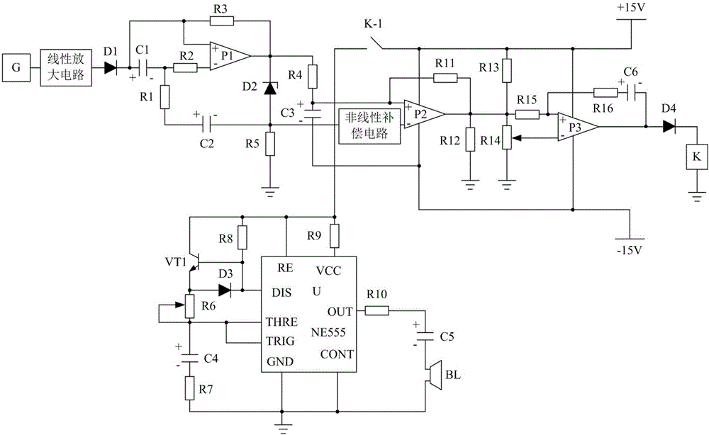
Figure 1 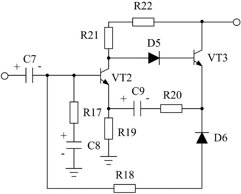
Figure 2 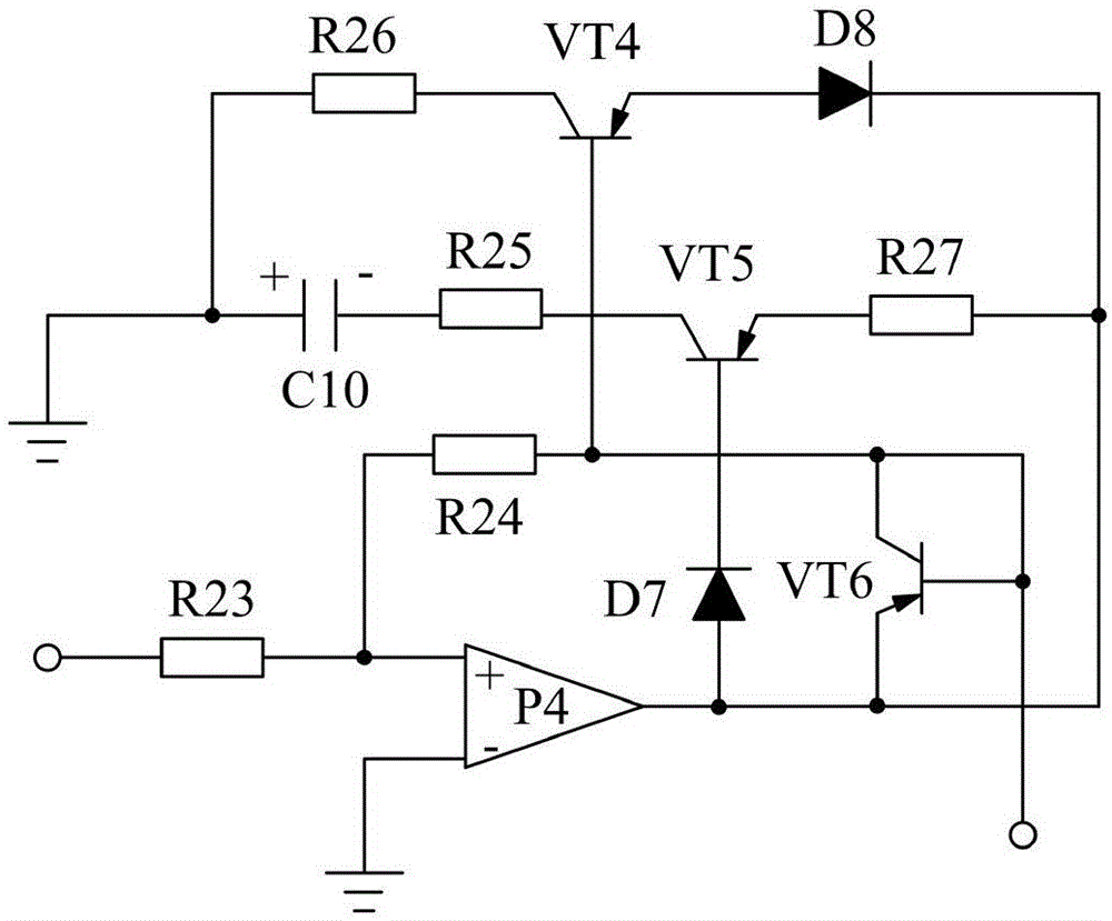
Figure 3
Abstract
Description
technical field
[0001] The invention relates to a monitoring and alarm system, in particular to a high-precision temperature monitoring and alarm system for growing figs in greenhouses. Background technique
[0002] Figs are rich in nutrients such as amino acids, organic acids, magnesium, manganese, copper and vitamins, and are deeply loved by people. With the development of greenhouse planting technology, figs have been planted in greenhouses. If figs are planted in greenhouses, the yield of figs will increase, and the fruit will be larger and the juice will be more. Because figs are not cold-resistant and have high temperature requirements, a temperature monitoring system is usually used to monitor the temperature in the greenhouse when planting in a greenhouse. When the temperature is too low, the greenhouse needs to be heated in time to ensure the normal growth of figs. However, the existing temperature monitoring system is doped with a large noise signal in the signal ...
Examples
Embodiment
[0019] Such as figure 1 As shown, the present invention mainly consists of a temperature sensor G, a trigger switch circuit, a nonlinear compensation circuit connected with the trigger switch circuit, a linear amplifier circuit connected with the temperature sensor G, an amplifier P1, and the P pole is connected with the linear amplifier circuit, The diode D1 whose N pole is connected to the output terminal of the amplifier P1 after passing through the resistor R3, the positive pole is connected with the N pole of the diode D1, the negative pole is connected with the negative pole of the amplifier P1 after passing through the resistor R2, and the N pole is connected with the amplifier P1. The output terminal is connected, the P pole is grounded after the resistor R5, and the positive pole is connected to the negative pole of the capacitor C1 after the resistor R1, and the negative pole is connected to the P pole of the Zener diode D2. Capacitor C2, the positive pole is connecte...