
Screw compressor for mixed refrigeration field and application method thereof
The technology of a screw compressor and its application method, which is applied in the field of screw compressors, can solve problems such as short maintenance period, high noise frequency, and large cooling water consumption, and achieve the effects of convenient operation and maintenance, good dynamic balance, and high degree of automation
Patent Information
- Authority / Receiving Office
- CN · China
- Patent Type
- Applications(China)
- Current Assignee / Owner
- Publication Date
- 2017-04-19
- Estimated Expiration
- Not applicable · inactive patent
Smart Images

Figure 1 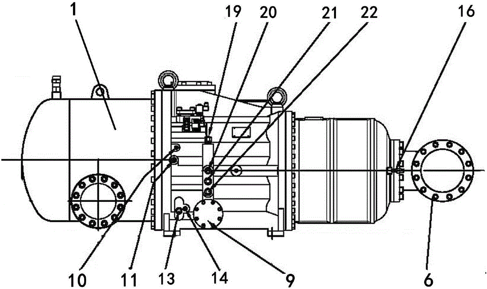
Figure 2 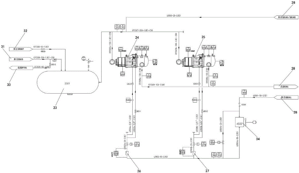
Figure 3
Abstract
Description
[0001] Technical field:
[0002] The invention belongs to the technical field of natural gas liquefaction, and in particular relates to a screw compressor used in the field of mixed refrigeration and an application method thereof.
[0003] Background technique:
[0004] Screw compressors are divided into single-screw compressors and twin-screw compressors. The commonly used screw compressor is an oil-filled screw compressor. When the compressed gas medium does not react with the lubricating oil and the lubricating oil can be mixed into the medium and can be separated well, the oil-injected screw machine is used, and the screw machine does not set synchronous gears. , The compressor cavity is connected with the lubricating oil system, and a swipe valve is usually set, which can not only adjust the exhaust pressure to adapt to various working conditions, but also greatly reduce energy consumption. The dry seal is used between the main engine and the main shaft, so that there is ...
Examples
Embodiment Construction
[0025] The technical solution of the present invention will be described in detail below in conjunction with the accompanying drawings and specific embodiments.
[0026] Such as figure 1 , figure 2 As shown, the screw compressor for mixed refrigerant compression includes a body 1, on which a cylinder 2, a piston 3, a connecting rod 4, and a body compression chamber 5 are installed, and the connecting rod 4 and the piston 3 are firmly connected to the body 1 Above, the suction inlet flange 6 is provided on the cylinder 2, and the junction box 7 is provided on the outer wall of the compression chamber 5 of the body. device 10, injection port 11 of the mechanical compression chamber, cleaning hole cover flange, and oil drain valve, the capacity regulating solenoid valve 8 is connected to the economizer interface 12, and the side of the mechanical filter 9 is provided with an oil level sight glass 13 and An oil balance valve 14; a horizontal check valve is installed on one side...