
Lifting base bracket
A technology of seat bracket and base, which is applied in the field of mechanical parts processing, and can solve the problem that the support frame does not have a calibration structure.
Patent Information
- Authority / Receiving Office
- CN · China
- Patent Type
- Applications(China)
- Current Assignee / Owner
- Publication Date
- 2017-08-18
Smart Images
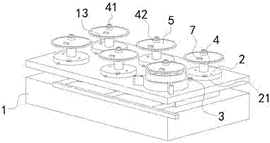
Figure 1 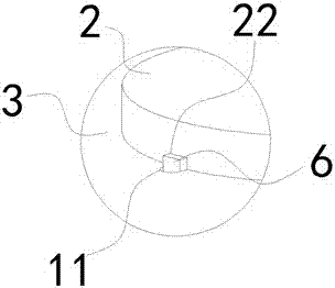
Figure 2 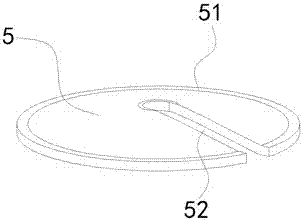
Figure 3
Abstract
Description
technical field
[0001] The invention relates to the field of machining of mechanical parts, in particular to a lifting seat bracket. Background technique
[0002] At present, the drill bit of the hole drilling machine is slender, and the two ends of the drill bit are respectively subjected to torque in opposite directions. When the guide rail of the deep hole drilling machine slides to process deep holes, the relative position of the main shaft and the guide rail is prone to deviation under the action of torsional force, which makes the main shaft and the drill bit vibrate, resulting in drilling deviation and drill bit damage. Therefore, During processing, the stability of the spindle is poor, the processing precision is low, and it takes a lot of debugging time, which reduces the production efficiency.
[0003] Now the publication number is CN203292932U, which discloses a support frame for positioning the main shaft of a deep hole drilling machine, including a bracket and ...
Examples
Embodiment 1
[0031] Embodiment one, such as figure 1 , figure 2 , image 3 and Figure 4 The lifting seat bracket has a workbench 1, and several bases 2 are arranged on the workbench 1, and the base 2 is riveted on the workbench 1 through rivets. This application considers the cost and the time consumed for replacing the processing parts, and now we can set up six A base of 2 is the optimal setting. Fixing pieces 13 are arranged on the workbench 1 around the base 2 to fix the processing parts.
[0032] A calibration structure 3 is provided between the base 2 and the workbench 1. The calibration structure 3 includes lower and upper channels 11 and 22 respectively set on the workbench 1 and the base 2, and between the lower and upper channels 11 and 22. A calibration block 6 is provided, and is riveted with the workbench 1 by penetrating the base 2 and the calibration block 6 with two rivets. The calibration block 6 is partly outside the base 2 and exposed on the workbench 1 .
[0033...
Embodiment 2
[0037] In the second embodiment, on the basis of the first embodiment, an outer edge 51 is provided on the detachable pressure plate 5 to fit the processed parts. The outer edge 51 can be fixed on the outermost side of the detachable pressure plate 5 to wrap the processed parts, and the outer edge 51 can also be fixed on the inner side of the detachable pressure plate 5 to support the inner cavity of the processed parts.
Embodiment 3
[0038] Embodiment three, such as figure 1 , figure 2 , image 3 and Figure 4 The detachable pressure plate 5 is provided with a synchronous supercharging device 7 to realize the close fit between the detachable pressure plate 5 and the processing parts. The synchronous supercharging device 7 has six evenly distributed around the detachable pressure plate 5 . The synchronous supercharging device 7 has a vacuum suction cup 71, the tail of the vacuum suction cup 71 is provided with a cavity, a rubber piston is placed in the cavity, a connecting rod is fixed on the rubber piston, and the connecting rod extends out of the surface of the detachable pressure plate 5 to connect to the cross bar; The tail of the vacuum suction cup 71 is connected with an ejection structure 72, and the ejection structure 72 has an ejection cavity, and a rubber piston is arranged in the ejection cavity, and an ejection connecting rod is fixed on the rubber piston, and the ejection connecting rod and t...