
Ultrasound air floating type sewage treatment equipment
A sewage treatment equipment, air flotation technology, applied in water/sewage treatment equipment, flotation water/sewage treatment, water/sewage treatment, etc. Complex structure and high operating costs, to achieve the effect of low operating costs, high degree of automation, and enhanced speed and efficiency
Patent Information
- Authority / Receiving Office
- CN · China
- Current Assignee / Owner
- Publication Date
- 2018-07-03
- Estimated Expiration
- Not applicable · inactive patent
Smart Images
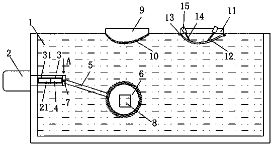
Figure 1 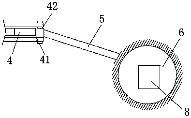
Figure 2
Abstract
Description
technical field
[0001] The invention relates to the technical field of sewage treatment equipment, in particular to ultrasonic air flotation sewage treatment equipment. Background technique
[0002] The air flotation machine is a kind of equipment for removing suspended solids, grease and various jelly in various industrial and municipal sewage. The equipment is widely used in the treatment of industrial waste water and municipal sewage such as oil refining, chemical industry, brewing, slaughtering, electroplating, printing and dyeing.
[0003] The air flotation machine is a dissolved air system that produces a large number of fine bubbles in the water, so that the air attaches to the suspended particles in the form of highly dispersed tiny bubbles, resulting in a state of density lower than that of water. -Water treatment equipment for liquid separation. The air flotation machine is divided into super-efficient shallow air flotation machine, vortex concave air flotation m...
Examples
Embodiment Construction
[0016] In order to deepen the understanding of the present invention, the present invention will be further described below in conjunction with the accompanying drawings and embodiments, which are only used to explain the present invention and do not limit the protection scope of the present invention.
[0017] Such as figure 1 As shown, the ultrasonic air flotation sewage treatment equipment includes an air flotation tank 1, and a motor 2 installed on the side of the air flotation tank 1, and also includes a support arm 3, a swing rod 4, a swing arm 5 and an air float ball 6, wherein: the motor 2 , is fixed on the side of the air flotation pool 1, and its output shaft 21 is fixed on one end of the swing rod 4; the support arm 3, fixed at the position of the air flotation pool 1 corresponding to the swing rod 4, is provided with a horizontal chute 31; the swing rod 4, One end connected to the motor 2 is located in the chute 31 of the support arm 3 and slides horizontally left ...