
Auto-excitation type DC-DC converter with switch located at input side
A DC-DC, input-side technology, applied in the direction of converting DC power input to DC power output, output power conversion devices, instruments, etc., to meet the needs of power conversion and reduce the effect of requirements
Patent Information
- Authority / Receiving Office
- CN · China
- Current Assignee / Owner
- Publication Date
- 2018-08-10
- Estimated Expiration
- Not applicable · inactive patent
Smart Images
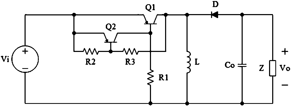
Figure 1 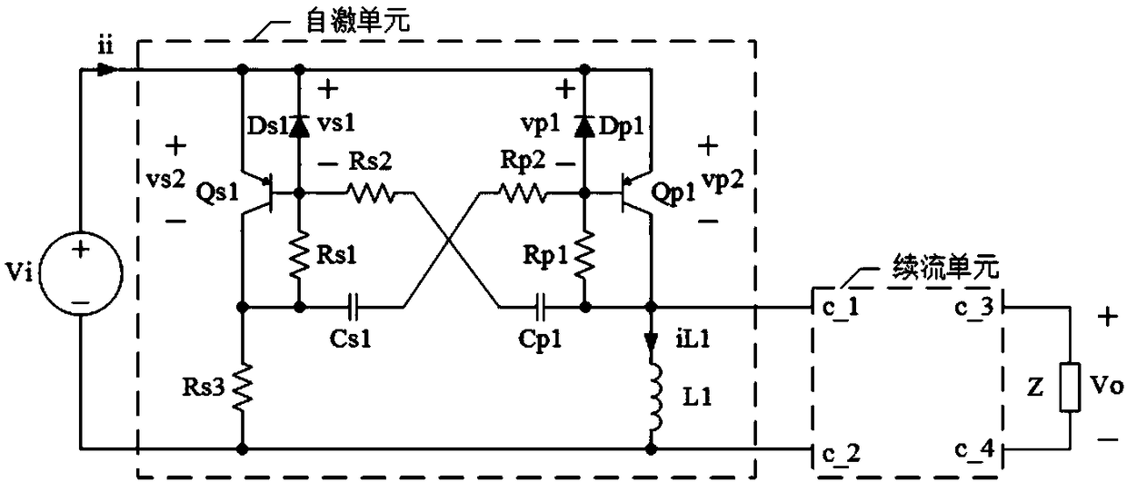
Figure 2 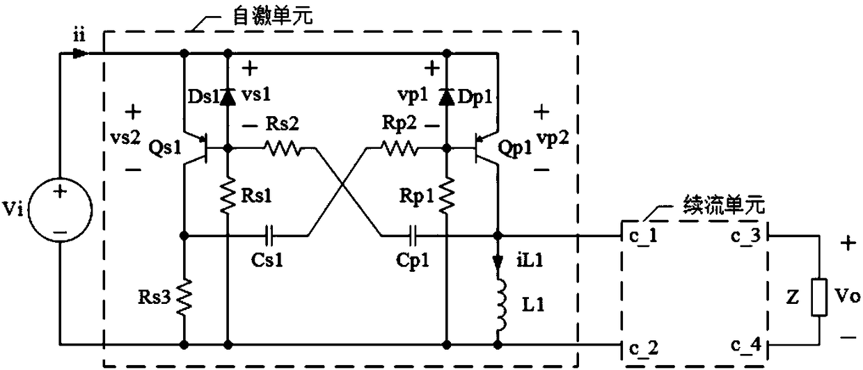
Figure 3
Abstract
Description
technical field
[0001] The invention relates to a DC-DC converter with a switch located on the input side, which is suitable for low-power working occasions and applicable fields such as energy collection, LED driving, auxiliary power supply and the like. Background technique
[0002] Common DC-DC converters with switches on the input side include Buck-Boost converters, Zeta converters, and Flyback converters. Compared with other excited DC-DC converters, self-excited DC-DC converters have the advantage of cost performance. like figure 1 As shown, an existing self-excited Buck-Boost converter consists of resistors R1 to R3, PNP type BJT tubes Q1 and Q2, inductor L, diode D and capacitor Co. The circuit structure of the converter is simple, but whether the whole converter can start to vibrate smoothly is directly related to the values of R2 and R3. When R2 and R3 are improperly designed, it will cause the consequences that the entire converter cannot start to vibrate smo...
Examples
Embodiment 1
[0026] refer to figure 2 , a self-excited DC-DC converter with a switch on the input side, including a self-excited unit and a freewheeling unit, the self-excited unit includes resistors Rs1 to Rs3, resistors Rp1, resistors Rp2, capacitor Cs1, capacitor Cp1, diode Ds1, diode Dp1, inductor L1, PNP type BJT tube Qs1 and PNP type BJT tube Qp1, the freewheeling unit has port c_1, port c_2, port c_3 and port c_4, and the function of the freewheeling unit is when When the PNP type BJT transistor Qp1 is cut off, it provides a current path for the inductor L1.
[0027] The emitter of the PNP-type BJT tube Qs1 is simultaneously connected to the positive terminal of the DC power supply Vi, the cathode of the diode Ds1, the cathode of the diode Dp1 and the emitter of the PNP-type BJT tube Qp1, and the base of the PNP-type BJT tube Qs1 is simultaneously connected to the diode The anode of Ds1, one end of resistor Rs1 is connected with one end of resistor Rs2, the collector of PNP type B...
Embodiment 2
[0032] refer to image 3 In Embodiment 2, the other end of the resistor Rs1 is connected to the negative end of the DC power supply Vi, and the other end of the resistor Rp1 is connected to the negative end of the DC power supply Vi. All the other structures of embodiment 2 are the same as embodiment 1, and its working process is also similar to embodiment 1.
[0033] refer to Figure 7 , when the third preferred scheme of the freewheeling unit is adopted, Embodiment 2 essentially becomes a self-excited Flyback converter. The freewheeling unit includes an inductor Lc1, a diode Dc1 and a capacitor Cco, one end of the inductor Lc1 is connected to the anode of the diode Dc1, the cathode of the diode Dc1 is simultaneously connected to one end of the capacitor Cco and the port c_3 of the freewheeling unit, and the capacitor The other end of Cco is connected to the other end of the inductor Lc1 and the port c_4 of the freewheeling unit at the same time, the inductor Lc1 and the in...
Embodiment 3
[0036] refer to Figure 4 , the port c_2 of the freewheeling unit described in Embodiment 3 is connected to the port c_4, the other end of the resistor Rs1 is connected to one end of the load Z, and the other end of the resistor Rp1 is connected to one end of the load Z. The rest of the structure of embodiment 3 is the same as embodiment 2, and its working process is also similar to embodiment 2.
[0037] refer to Figure 5 , when the first preferred scheme of the freewheeling unit is adopted, Embodiment 3 essentially becomes a self-excited Buck-Boost converter. The freewheeling unit includes a diode Da1 and a capacitor Cao, the cathode of the diode Da1 is connected to the port c_1 of the freewheeling unit, and the anode of the diode Da1 is simultaneously connected to one end of the capacitor Cao and the port c_3 of the freewheeling unit The other end of the capacitor Cao is connected to the port c_2 and the port c_4 of the freewheeling unit at the same time. In the steady ...