
A rotatable probe bending structure for endoscope
A rotary, endoscope technology, applied to endoscopes, gastroscopes, applications, etc., can solve the problems of rigid endoscopes that cannot flexibly change directions, the imaging effect is not as good as rigid endoscopes, and cannot be observed in specific parts. , to achieve the effect of improving the utilization rate of the ring, reducing the space required for work, and being easy to operate.
Patent Information
- Authority / Receiving Office
- CN · China
- Patent Type
- Patents(China)
- Current Assignee / Owner
- Publication Date
- 2020-05-22
Smart Images
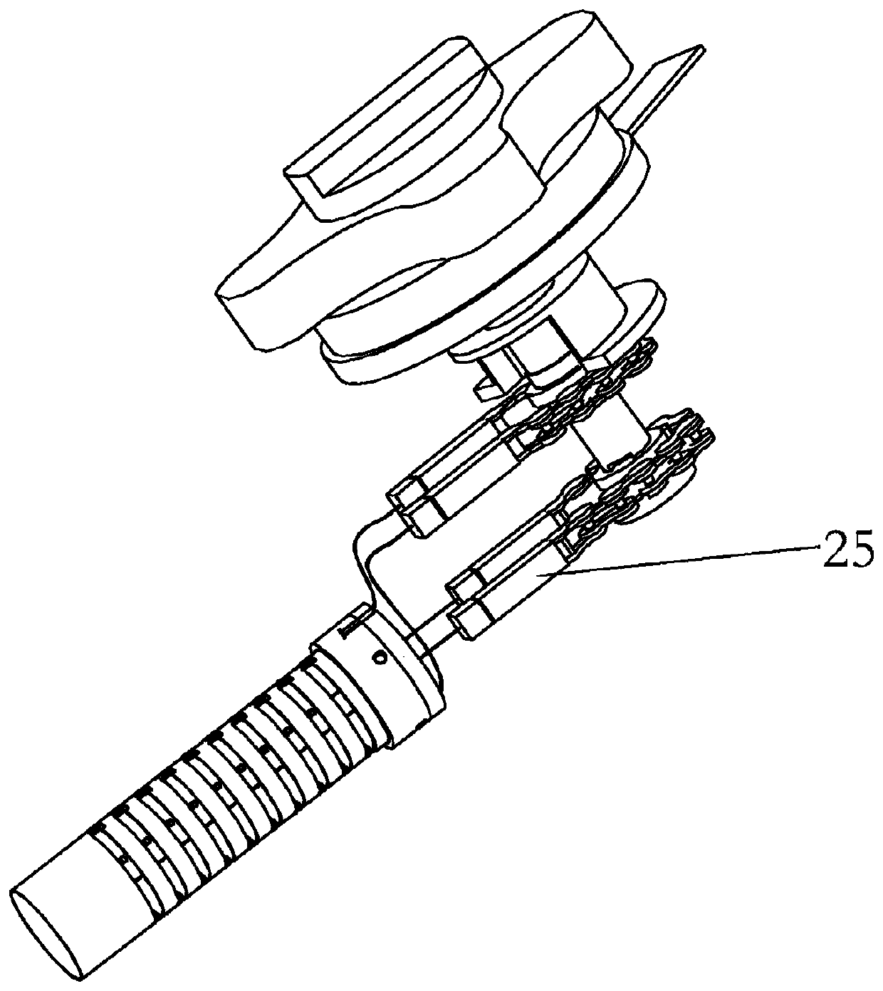
Figure 1 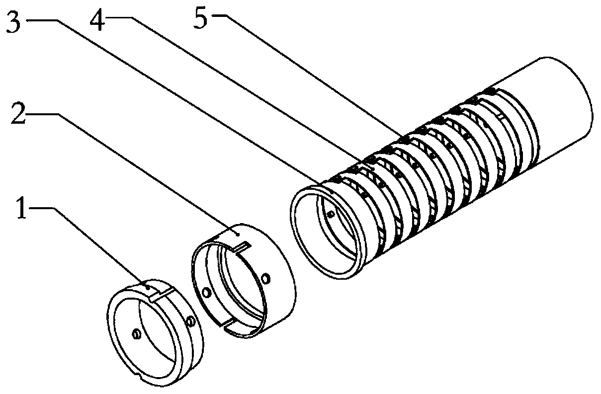
Figure 2 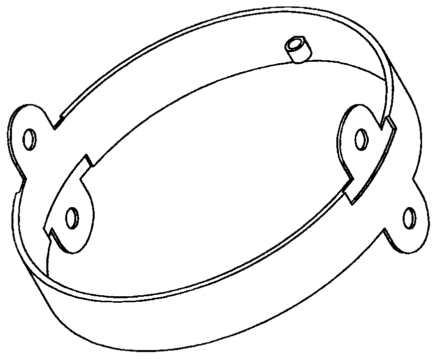
Figure 3
Abstract
Description
technical field
[0001] The invention relates to a probe device, in particular to a rotatable probe bending structure for an endoscope, which can be applied to a medical endoscope for gastrointestinal examination. Background technique
[0002] The gastrointestinal tract is the largest immune organ in the human body, and it is also the largest detoxification organ in the human body. In recent years, gastric cancer, colon cancer, and esophageal cancer have become the top ten cancers in the incidence of malignant tumors. Observing the surface structure of the digestive tract mucosa is of great significance to the discovery and treatment of cancer. Endoscopy plays a key role in this field. It has been widely used in clinical treatment.
[0003] Existing endoscopes can be divided into two types, i.e. rigid endoscopes and soft endoscopes. The rigid endoscope is a prism optical system, and the biggest advantage is that the image is clear, but the rigid endoscope itself cannot ch...
Examples
Embodiment Construction
[0034] The present invention will be further described below in conjunction with the accompanying drawings.
[0035] Such as figure 1 As shown, an embodiment of the invention includes a probe tip portion and a pull handle portion.
[0036] Such as figure 2 As shown, the end part of the probe includes a top cover cylinder 1, a bottom support sleeve 2, a connecting sleeve 3 and a ring 4 which are sequentially connected coaxially, the top cover cylinder 1 and the bottom support sleeve 2 are threaded, and the other end of the bottom support sleeve 2 and the One end of the connecting sleeve 3 is rotatably socketed, and a plurality of circular rings 4 are coaxially connected in series and then hinged to the other end of the connecting sleeve 3; the two outer walls of the top cover tube 1 are symmetrically provided with two strip grooves, the top The end surface of the cover tube 1 close to the bottom support sleeve 2 is provided with an annular groove for constraining and accommo...