
Self-disturbance rejection controller designing method capable of overcoming gap nonlinearity
An active disturbance rejection controller, nonlinear technology, applied in the direction of adaptive control, general control system, control/regulation system, etc., can solve problems such as limit cycle oscillation, achieve simple implementation, avoid limit cycle oscillation, and good adaptability Effect
Patent Information
- Authority / Receiving Office
- CN · China
- Current Assignee / Owner
- Publication Date
- 2019-02-19
- Estimated Expiration
- Not applicable · inactive patent
Smart Images
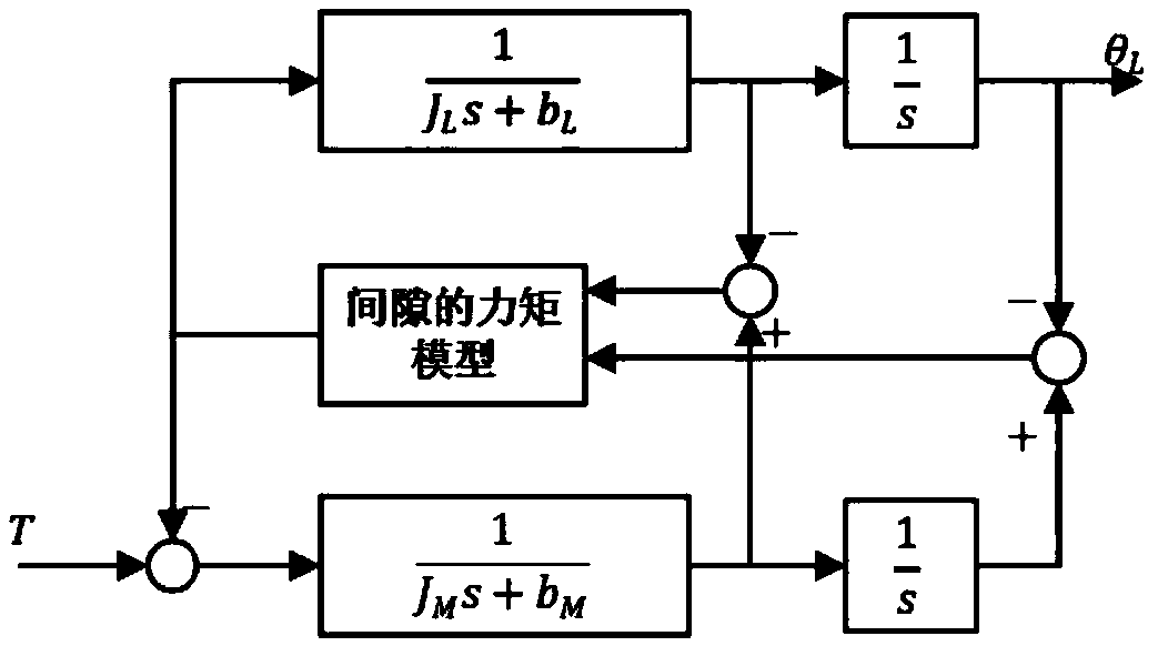
Figure 1 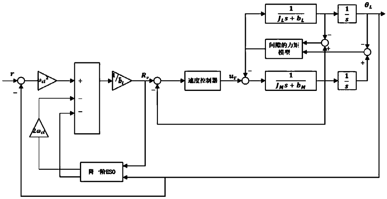
Figure 2 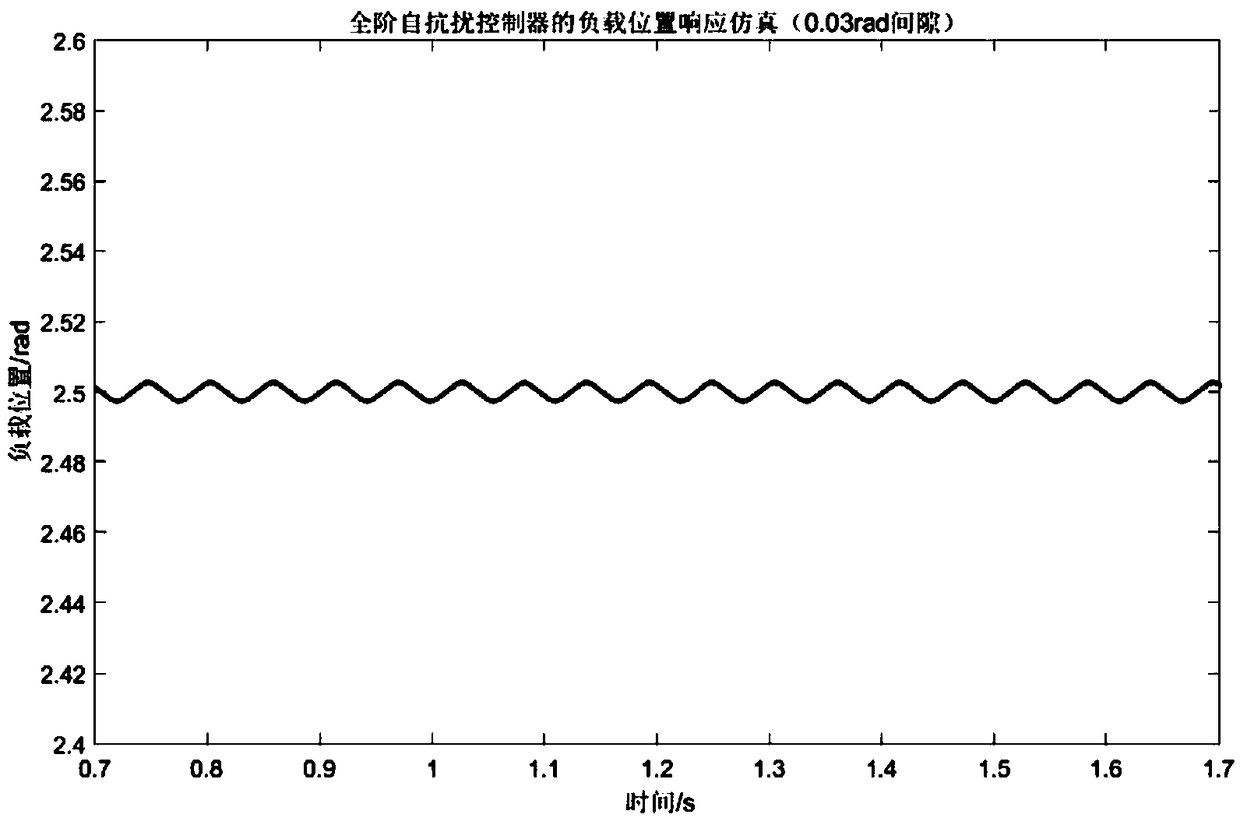
Figure 3
Abstract
Description
technical field
[0001] The invention belongs to the technical field of high-precision servo control, and relates to a design method of an active disturbance rejection controller for overcoming gap nonlinearity. Background technique
[0002] In an automatic control system, gaps or gap-like nonlinearities inevitably exist in the system. Taking the servo system as an example, the connection between the actuator and the controlled object is mostly through transmission links such as gears, toothed belts or worms. In this kind of system, the transmission gap inevitably becomes the most important nonlinear factor, and due to its non-differentiable and non-smooth characteristics, the transmission gap cannot be linearized and the compensation is difficult. The processing methods for the gap can be roughly divided into two types: Two categories, the first category is through precision mechanical structure design and post-lubrication method, but the cost is high. If the transmission ...
Examples
Embodiment
[0041] 1. Algorithm design and simulation:
[0042] figure 1 It is a block diagram of a two inertia system (Two Inertia System) with a gap, and the nonlinear link of the gap exists in the gear transmission between the motor shaft and the load shaft, where J M is the moment of inertia of the motor, J L is the moment of inertia of the load, b M is the motor damping, b L is the load damping, T is the input torque, θ M is the motor shaft position output, θ L Output for the load shaft position. The moment model of the gap is:
[0043]
[0044] in, That is, the displacement difference between the motor shaft and the load shaft after being converted to the load side according to the transmission ratio, g r is the transmission ratio, T s is the shaft transmission torque, α is the size of the transmission gap, k and c represent the gear elastic coefficient and damping coefficient respectively.
[0045] First, the basic model of the controlled object is established, and th...