
An Optimal Design Method for External Grid Connection Scheme of Electrified Railway
A technology for electrified railways and external power grids, applied in the direction of circuit devices, AC network circuits, multi-phase network asymmetry reduction, etc., can solve the non-global optimal or satisfactory solution of external power grid access schemes, waste of resources, and failure to guarantee PCC and other problems, to achieve the effects of easy solution and calculation, saving investment and reducing compensation capacity
Patent Information
- Authority / Receiving Office
- CN · China
- Patent Type
- Patents(China)
- Current Assignee / Owner
- Publication Date
- 2022-03-15
Smart Images
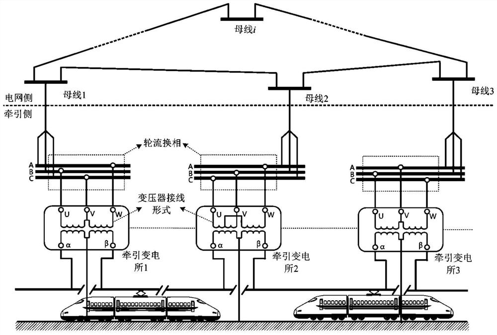
Figure 1 
Figure 2 
Figure 3
Abstract
Description
technical field
[0001] The invention relates to the field of optimal design of a traction power supply system, in particular to an optimal design method for an external grid connection scheme of an electrified railway. Background technique
[0002] The 25kV power frequency single-phase traction power supply system is the core component of the electrified railway. However, as more and more high-speed railway lines are put into operation, the power quality problems caused by the traction power supply system in the public grid are becoming more and more prominent, especially the problem of voltage imbalance. This problem is particularly prominent in the central and western regions of China where the power grid structure is weak. Therefore, in the design stage of the traction power supply system, it is necessary to focus on how to solve the voltage imbalance problem generated by it, and at the same time meet the requirements of economy.
[0003] The external grid connection sc...
Examples
Embodiment
[0091] The topological structure of the embodiment in the present invention is as figure 1 shown. Comparing three external power grid access schemes, the combination u of the traction transformer wiring form in each traction substation is shown in Table 2.
[0092] Table 2. Traction transformer wiring combination u
[0093]
[0094] The commutation combination w of each traction substation is shown in Table 3
[0095] Table 3. Alternative Commutation Combination w
[0096]
[0097] The parameters of the three-phase power grid are shown in Table 4.
[0098] Table 4. Three-phase grid parameters
[0099]
[0100] After programming calculation, the calculation results are shown in Table 5.
[0101] Table 5. Calculation results
[0102]
[0103] Table 4 shows the calculation results of three external grid access schemes; according to Table 4, it can be known that the external grid access scheme f(w 2 ,u 2 ) is the global optimal scheme, the capacity of the negat...