
Straight-flow suction gust wind tunnel with bypasses
A gust and wind tunnel technology, applied in the field of gust wind tunnel experimental devices, can solve problems such as hindering measurement, turbulent flow, and unstable wind environment, and achieve the effect of reducing unstable interference
Patent Information
- Authority / Receiving Office
- CN · China
- Patent Type
- Applications(China)
- Current Assignee / Owner
- Publication Date
- 2019-05-24
Smart Images
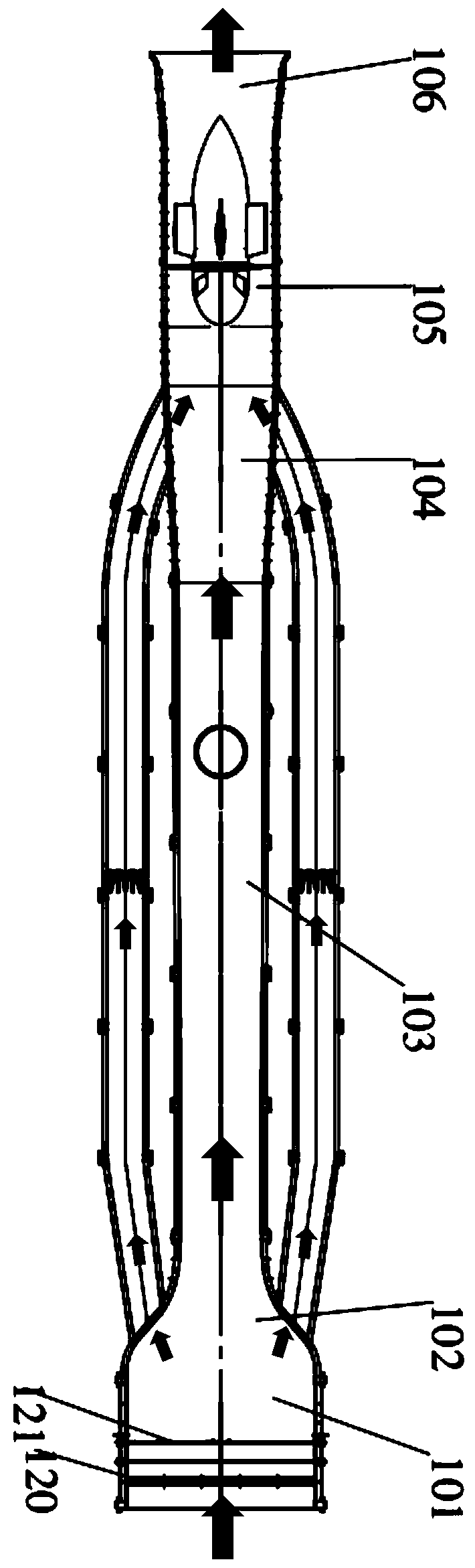
Figure 1 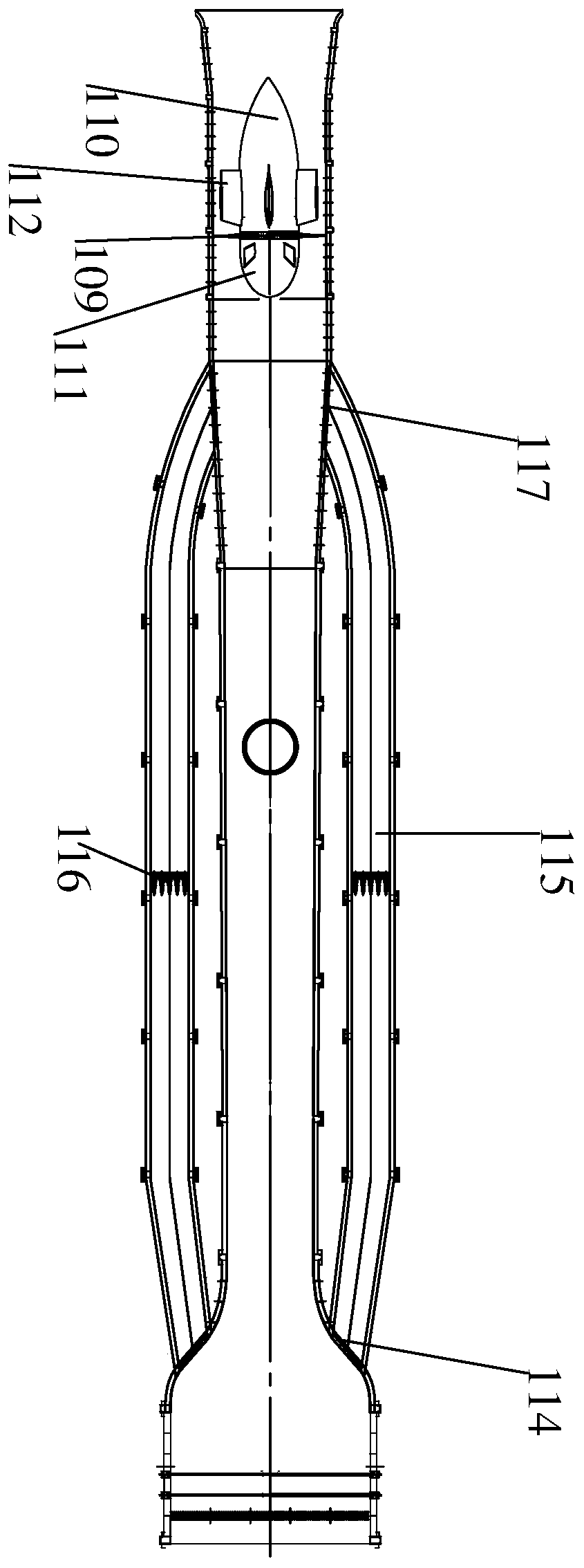
Figure 2 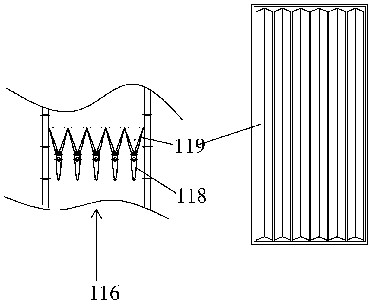
Figure 3
Abstract
Description
technical field
[0001] The present invention relates to a kind of gust wind tunnel experimental device, more specifically, it relates to a kind of direct current suction gust wind tunnel with bypass. Background technique
[0002] Simply put, a wind tunnel is a specially designed long pipe, which generates an airflow that can be controlled freely by the power system (motor and fan) inside it, and uses it to simulate the flow of air when objects move in the air Phenomena, the situation of objects under force, the phenomenon of air flow around certain fixed objects, and the migration and diffusion of smoke in the air, etc. ".
[0003] Air pollution, also known as air pollution, according to the definition of the International Organization for Standardization (ISO), air pollution usually refers to certain substances entering the atmosphere due to human activities or natural processes, presenting sufficient concentrations, reaching sufficient time, and Phenomena that are thus je...
Examples
Embodiment 1
[0042] The embodiment of the present invention proposes a direct-current suction gust wind tunnel with a bypass to realize gusts with high and low frequencies. Such as figure 1 When the suction-type DC gust tunnel in the embodiment of the present invention shown is in operation, the fan drives the fan 109 to rotate to generate an airflow. Controlling the opening of the shunt door 114 allows part of the airflow in the main channel to be sucked into the bypass channel 115 under the influence of the suction generated by the fan in the power section 101 after it moves. Also through the opening and closing of the movable vane 119 in the throttle valve 116 in the bypass passage 115, the air flow in the bypass passage changes, and then enters the diffuser section 104 communicating with the bypass passage 115 through the opening and closing door 117, so that The airflow flowing through the test section 103 changes instantaneously, forming gusts with varying wind speeds. When the ope...
Embodiment 2
[0053] In this embodiment, the throttle valve 116 in the first embodiment is replaced by a rotary throttle valve 216 , and the rotary throttle valve 216 includes an arc-shaped piece 219 and a rotating shaft 218 . The axial direction of the rotating shaft 218 is perpendicular to the wind direction in the bypass passage 115, and the arc-shaped piece 219 is fixedly connected with the rotating shaft 218 and can rotate with the rotation of the rotating shaft 218. By controlling the area blocked by the arc-shaped sheet 219 in the bypass passage 115 Size, to control the air flow in the bypass channel 115. The arc-shaped sheet 219 can rotate through the rotating shaft 218; the rotation of the arc-shaped sheet 219 is driven by controlling the rotation of the rotating shaft 218, thereby changing the size of the wind speed in the test section 103 to form a gust of wind speed.
[0054] The principle is as follows: Figure 5 When the direct-flow suction gust tunnel in the embodiment of th...