

Combined magnetic field arc ion plating and twin-target high-power pulse magnetron sputtering method
A high-power pulse and arc ion plating technology, which is applied in the field of material surface treatment, can solve the problems of large particle defects, limitation of deposition position and workpiece shape, low efficiency of arc plasma transmission, etc., to ensure uniformity and improve utilization efficiency Effect
Patent Information
- Authority / Receiving Office
- CN · China
- Current Assignee / Owner
- Publication Date
- 2019-07-09
Smart Images
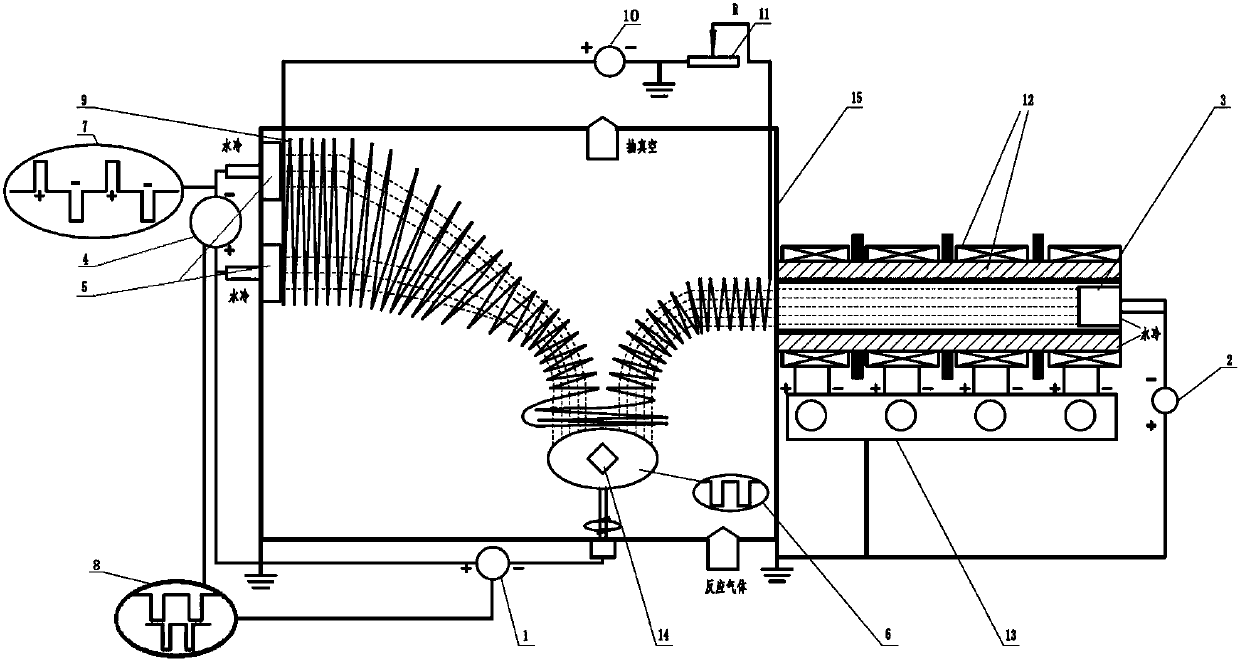
Figure 1 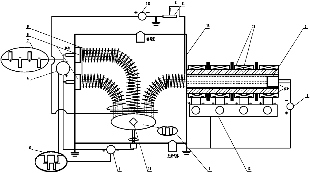
Figure 2 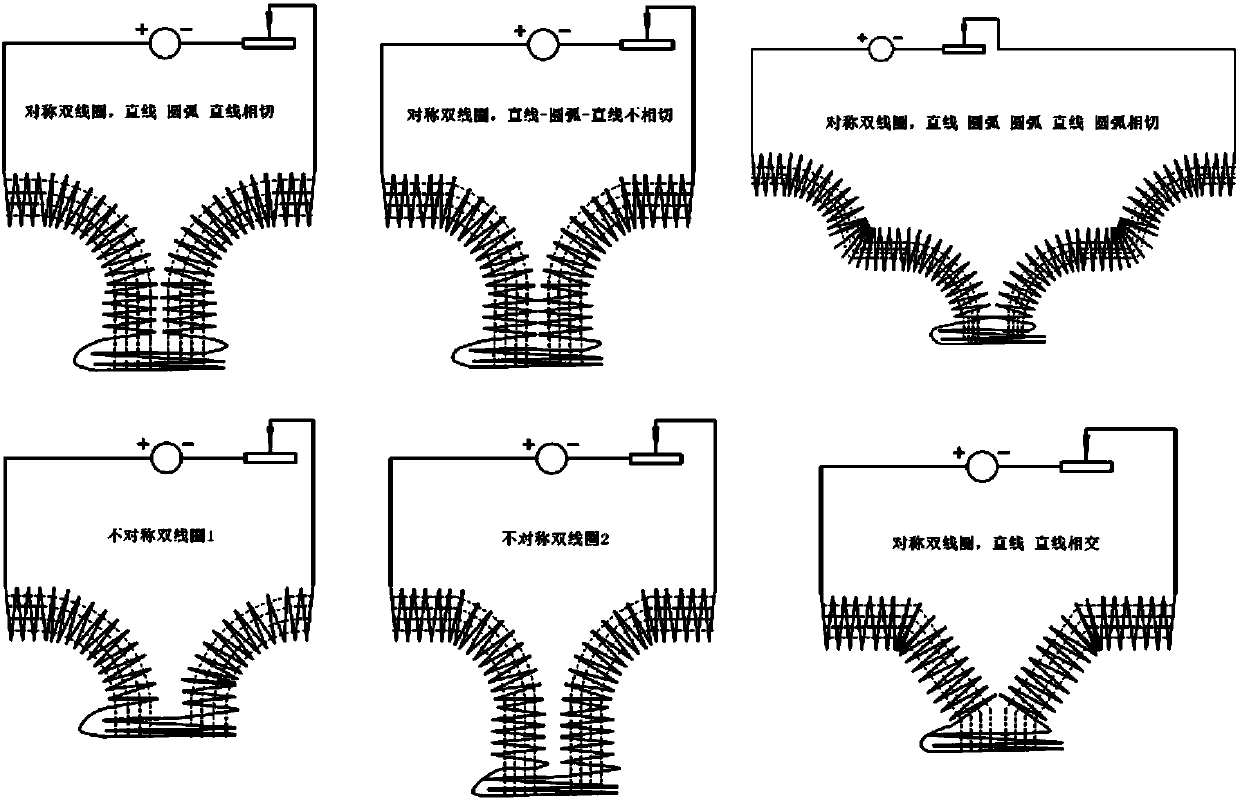
Figure 3
Abstract
Description
Technical field
[0001] The invention relates to a high-power pulse magnetron sputtering method for arc ion plating and twin target combined with a magnetic field, and belongs to the technical field of material surface treatment. Background technique
[0002] In the process of preparing thin film by arc ion plating, the current density of arc spot is as high as 2.5~5×10 10 A / m 2 , Causing molten liquid metal to appear at the arc spot on the surface of the target, which is sprayed out in the form of droplets under the action of the partial plasma pressure, attached to the surface of the film or embedded in the film to form "Macroparticles" (Macroparticles) Defects (BoxmanR L, Goldsmith S. Macroparticle contamination in cathodic arc coatings: generation, transport and control [J]. Surf Coat Tech, 1992, 52(1): 39-50.). In the arc plasma, since the moving speed of electrons is far greater than that of ions, the number of electrons reaching the surface of large particles per unit time ...
Examples
specific Embodiment approach 1
[0022] Specific implementation mode 1: the following combination Figure 1-5 To explain this embodiment, the device used in this embodiment combines a magnetic field arc ion plating and twin target high-power pulse magnetron sputtering method includes a bias power supply (1), an arc power supply (2), and an arc ion plating target source (3) , Twin target high power pulse magnetron sputtering power supply (4), twin target high power pulse magnetron sputtering target source (5), bias power waveform oscilloscope (6), twin target high power pulse magnetron sputtering power supply waveform Oscilloscope (7), waveform synchronization matching device (8), movable coil device (9), movable coil device power supply (10), rheostat device (11), multi-level magnetic field device (12), multi-level magnetic field device power supply (13) , Sample stage (14) and vacuum chamber (15);
[0023] In this device:
[0024] The substrate workpiece to be processed is placed on the sample table (14) in the ...
specific Embodiment approach 2
[0039] Second embodiment: The difference between this embodiment and the first embodiment is that the combined magnetic field arc ion plating is connected with the twin target high-power pulse magnetron sputtering composite deposition method, the arc power supply (2) is turned on, and the multi-level magnetic field device is turned on The power supply (13) adjusts the multi-level magnetic field device (12), turns on the movable coil device power supply (10), adjusts the movable coil device (9), adjusts the output resistance of the rheostat device (11), and the waveform synchronization matching device (8) controls the bias voltage The power supply (1) and the twin target high-power pulsed magnetron sputtering power supply (4) are turned on at the same time, the twin target high-power pulsed magnetron sputtering power supply (4) output pulse period is an integer multiple of the output pulse of the bias power supply (1) ,Such as Figure 5 As shown, the pulse period output by the tw...
specific Embodiment approach 3
[0040] Specific embodiment 3: The difference between this embodiment and the first embodiment is that the combined magnetic field arc ion plating is connected to the twin target high-power pulse magnetron sputtering composite deposition method, the arc power supply (2) is turned on, and the multi-level magnetic field device is turned on The power supply (13) adjusts the multi-level magnetic field device (12), turns on the movable coil device power supply (10), adjusts the movable coil device (9), adjusts the output resistance of the rheostat device (11), and the waveform synchronization matching device (8) controls the bias voltage The power supply (1) and the twin target high-power pulsed magnetron sputtering power supply (4) are turned on at the same time, the twin target high-power pulsed magnetron sputtering power supply (4) outputs high-power pulses and bias voltage pulses output by the bias power supply (1) The waveform phase is adjustable, such as Figure 5 As shown, when...