
Mask and preparation method thereof
A mask plate and plate body technology, which is applied in metal material coating process, vacuum evaporation plating, coating, etc., can solve problems such as uneven deformation and affecting the stability of alignment accuracy
Patent Information
- Authority / Receiving Office
- CN · China
- Current Assignee / Owner
- Publication Date
- 2019-12-31
Smart Images
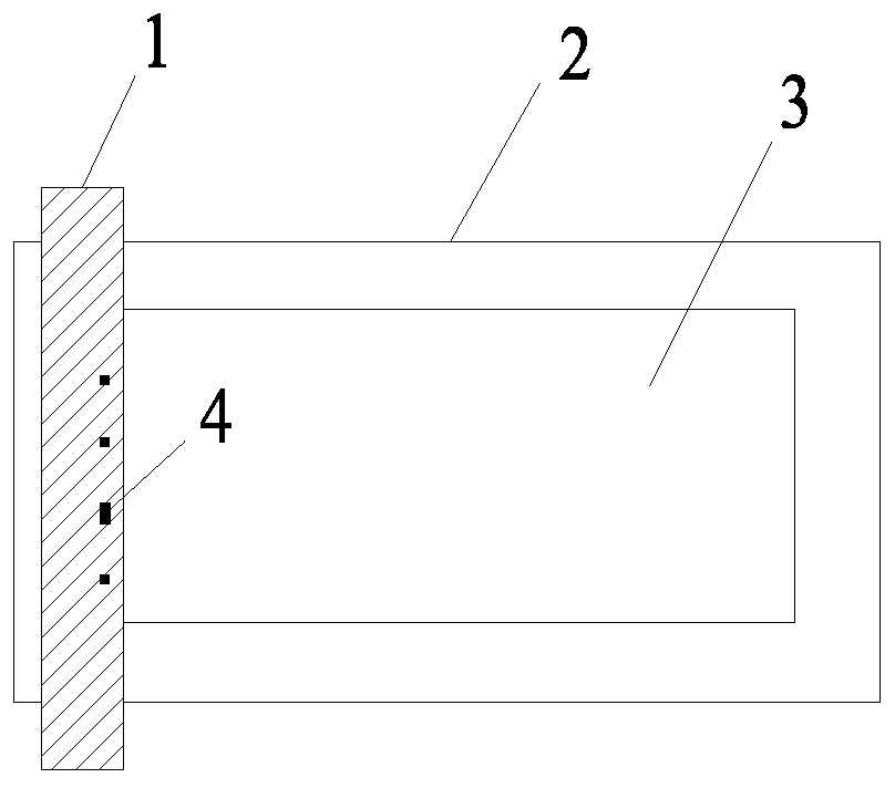
Figure 1 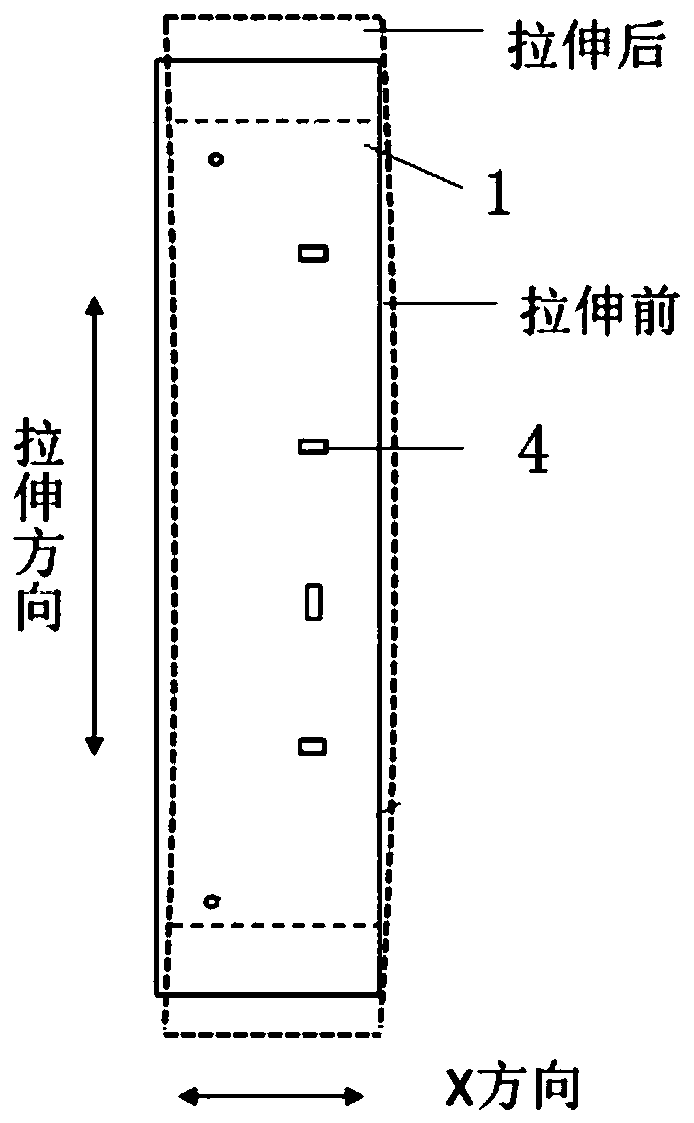
Figure 2 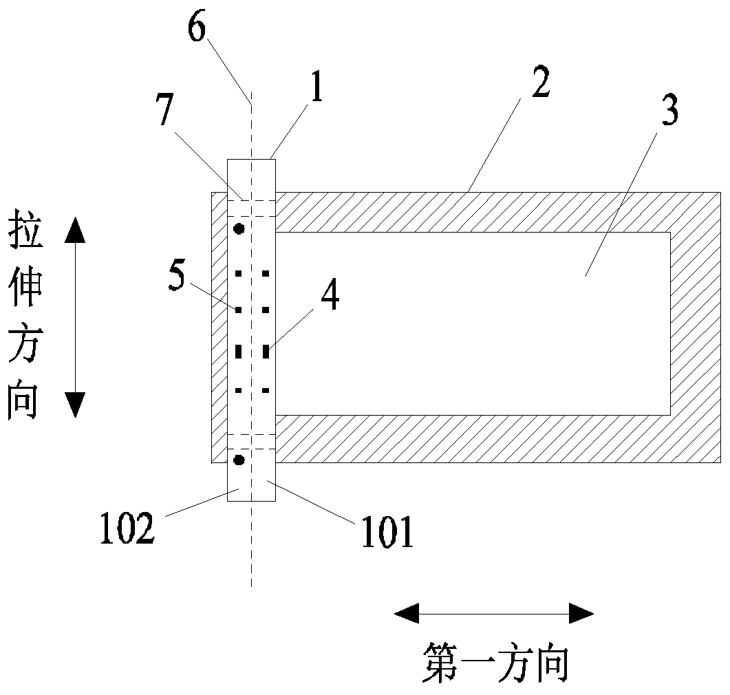
Figure 3
Abstract
Description
technical field
[0001] The invention relates to the field of display technology, in particular to a mask plate and a preparation method thereof. Background technique
[0002] Organic Light Emitting Diode (OLED) is the development trend of future display products, with a wide viewing angle, fast response, high brightness, high contrast, bright colors, light weight, thin thickness, low power consumption, etc. advantage. It has become the next-generation mainstream display technology after LCD (Liquid Crystal Display, liquid crystal display).
[0003] At present, vacuum thermal evaporation is an effective method for preparing OLED devices. It deposits the material molecules heated and evaporated through the opening of the mask device to the corresponding position of the back plate to obtain the required resolution. display panel.
[0004] The alignment mask in the mask device is mainly used for the detection of the evaporation process and the alignment of other evaporation d...
Examples
no. 1 example
[0041] image 3 It is a schematic structural diagram of a mask plate according to the first embodiment of the present invention. Such as image 3 As shown, the mask plate of the embodiment of the present invention includes a plate body 1 and a frame 2 , the frame 2 has an opening 3 , and the plate body 1 is welded on the frame 2 . The plate body 1 is in the shape of a rectangular strip, and the plate body 1 includes an effective vapor deposition area 101 corresponding to the opening 3 of the frame 2 and an ineffective vapor deposition area 102 corresponding to the border of the frame 2 . The evaporation effective area 101 and the evaporation ineffective area 102 are respectively located on both sides of the center line of the plate body 1 along the length of the first direction. The effective evaporation area 101 is provided with a detection opening 4 , and the inactive evaporation area 102 is provided with a balancing pattern 5 for balancing the tensile stress on the detect...
no. 2 example
[0053] Figure 6 It is a schematic diagram of the structure of the mask in the second embodiment of the present invention; Figure 7 It is a schematic structural diagram of the detection opening and the balance pattern in the mask plate according to the second embodiment of the present invention. This embodiment is an extension of the aforementioned first embodiment. The main structure of the mask plate in this embodiment is the same as that of the aforementioned first embodiment. The difference from the aforementioned first embodiment is that, as Figure 6 and Figure 7 As shown, the balance pattern 5 is a groove, and the shapes of the balance pattern 5 and the detection opening 4 are both rectangular. The area of the balance pattern 5 is larger than the area of the detection opening 4, so that the balance pattern 5 can balance the tensile stress on the detection opening 4, so that the deformation of the plate body 1 in the first direction is uniform during the stretchi...
no. 3 example
[0057] Figure 8 It is a schematic diagram of the structure of the mask plate in the third embodiment of the present invention; Figure 9 It is a schematic structural diagram of the detection opening and the balance pattern in the mask plate according to the third embodiment of the present invention. This embodiment is an extension of the aforementioned first embodiment. The main structure of the mask plate in this embodiment is the same as that of the aforementioned first embodiment. The difference from the aforementioned first embodiment is that, as Figure 8 and Figure 9 As shown, a balance pattern 5 and four detection openings 4 are arranged in the plate body 1 . The balance pattern 5 is a groove, and both the balance pattern 5 and the detection opening 4 are rectangular in shape. Wherein, the area of the balance pattern 5 is not less than the sum of the areas of the four detection openings 4, so that the deformation of the plate body 1 in the first direction is unif...