
High-reliability isolated high-voltage switching circuit
A high-voltage switch and isolation technology, applied in the field of high-reliability isolated high-voltage switch circuits, can solve the problems of control failure, property and casualties, etc., and achieve the effect of wide application and simple structure.
Patent Information
- Authority / Receiving Office
- CN · China
- Patent Type
- Applications(China)
- Current Assignee / Owner
- Publication Date
- 2020-08-07
Smart Images
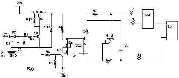
Figure 1 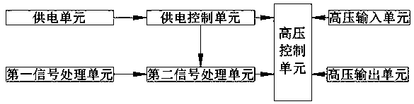
Figure 2
Abstract
Description
technical field
[0001] The invention relates to the technical field of switch circuits, more specifically, to a high-reliability isolated high-voltage switch circuit. Background technique
[0002] At present, all output control signals are basically sent to the control unit in the form of single-chip output. The core of this application is solved. When the control signal is abnormal or crashes and runs away, the control will fail. If the load cannot be timely Cutting off the output may cause serious consequences at the back end, causing property and personnel casualties. I just considered this. In order to avoid major property and personnel casualties, we will make an automatic crash or run away on the circuit. The control circuit to avoid. Contents of the invention
[0003] Aiming at the deficiencies and defects of the existing technology, a kind of application in the high-voltage input to high-voltage output side products is provided, and the small signal is used to con...
Examples
Embodiment Construction
[0017] The present invention will be further described below in conjunction with the accompanying drawings and specific embodiments.
[0018] see Figure 1-2 As shown, a kind of highly reliable isolated high voltage switch circuit of the present invention comprises:
[0019] The high-voltage control unit includes an optocoupler U1 and a triac control circuit, the triac control circuit includes a triac M1 whose G pole is connected to the controlled side of the optocoupler U1, and the triac T1 Pole and T2 are controlled by the main circuit of the load. When the optocoupler U1 is turned on, the bidirectional thyristor M1 is driven to output with load, and when the optocoupler U1 is turned off, the bidirectional thyristor M1 is driven to turn off the load;
[0020] The No. 1 pin of the optocoupler U1 is electrically connected to a first signal processing unit and a power supply control unit, the first signal processing unit includes an integrating circuit, and the input side of t...