
A high-efficiency automatic stacking mechanism based on smt production line
A fully automatic, production line technology, applied in the direction of conveyors, conveyor objects, transportation and packaging, etc., can solve the problems of low efficiency, waste of manpower, inconvenience of double-sided printing of printed circuit boards, etc., to expand the area , The effect of convenient lamination operation
Patent Information
- Authority / Receiving Office
- CN · China
- Patent Type
- Patents(China)
- Current Assignee / Owner
- Publication Date
- 2021-11-12
Smart Images
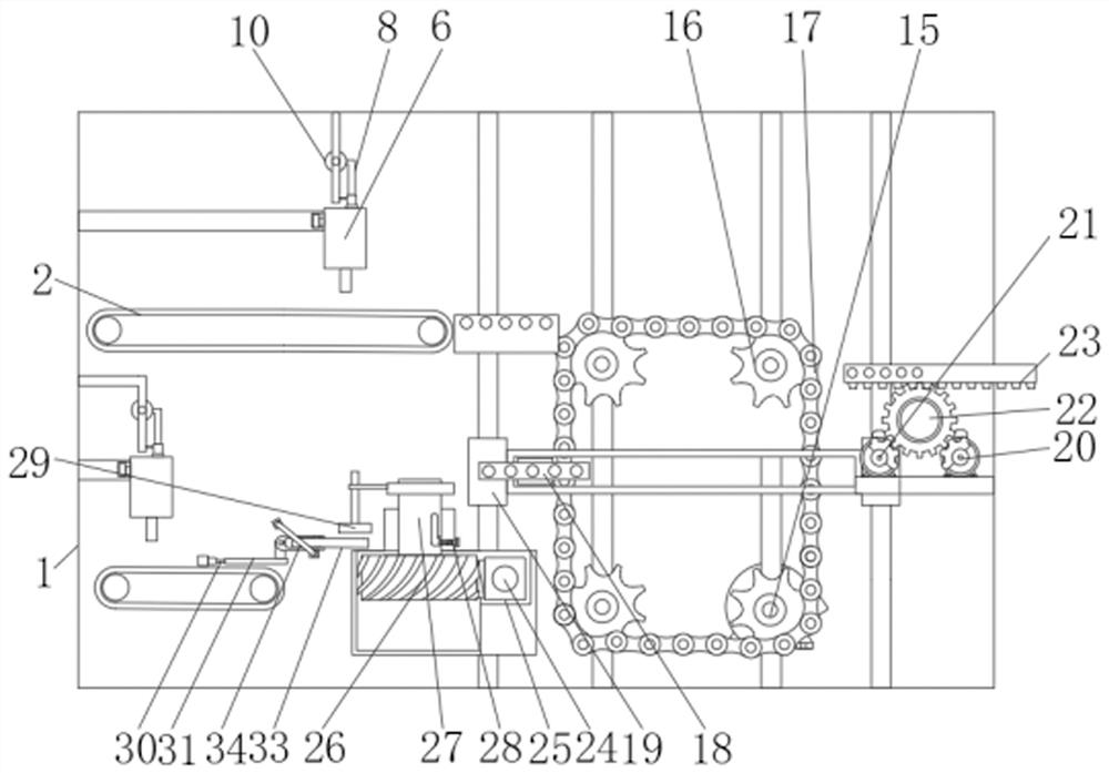
Figure 1 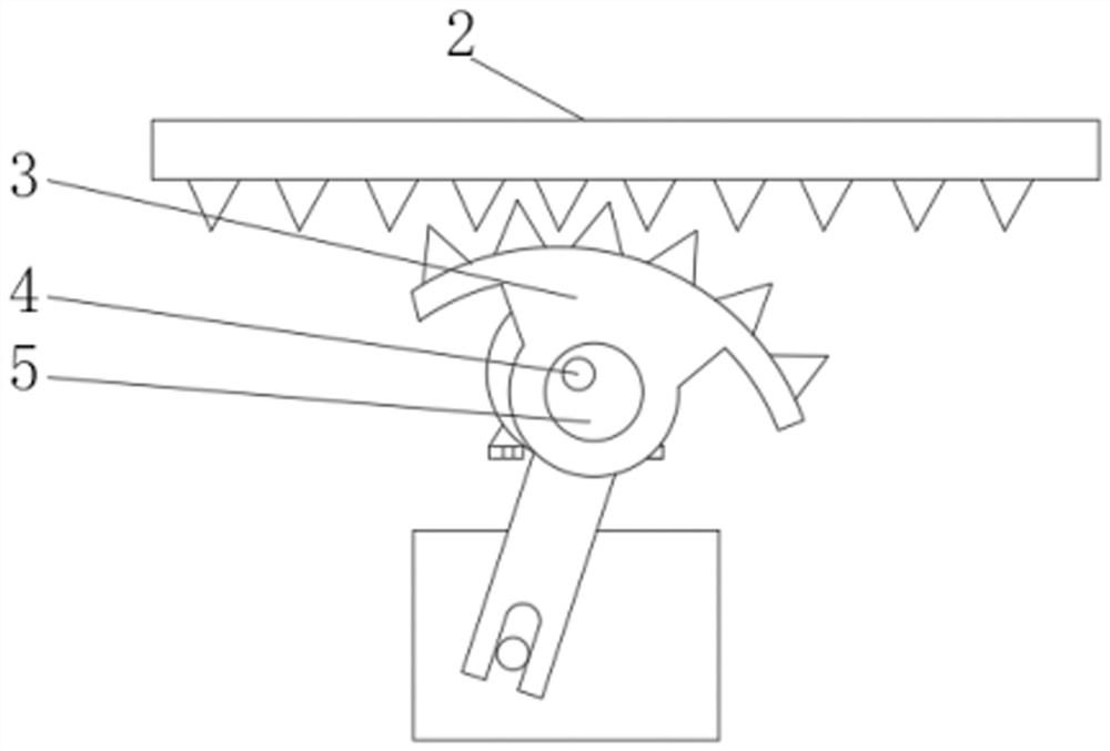
Figure 2 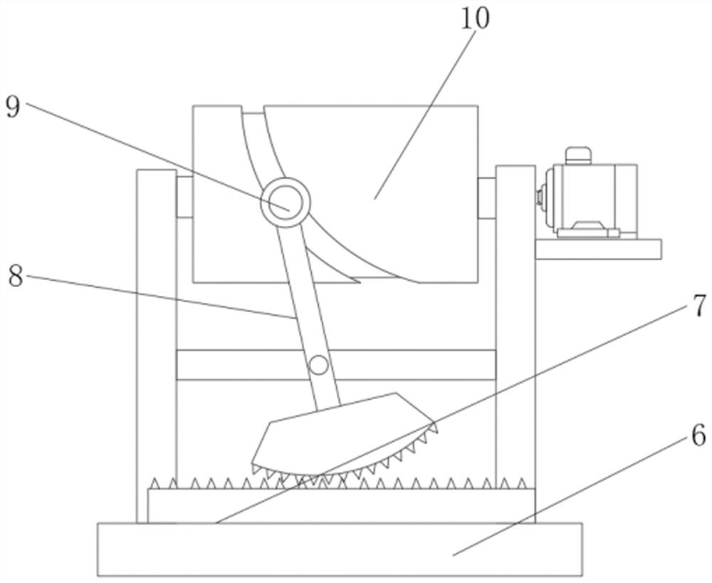
Figure 3
Abstract
Description
technical field
[0001] The invention relates to the technical field of fully automatic stack feeding, in particular to a high-efficiency fully automatic stack feeding mechanism based on an SMT production line. Background technique
[0002] SMT patch refers to the abbreviation of a series of process processes processed on the basis of PCB. It is the most popular technology and process in the electronic assembly industry. It is called surface mount or surface mount technology. Foot or short lead surface mount components are mounted on the surface of the printed circuit board or other substrates, and are soldered and assembled by reflow soldering or dip soldering.
[0003] After searching, the Chinese patent authorization number is CN201911203076.3 patent, which discloses a kind of SMT template automatic loading and unloading equipment and control method, including lifting frame, shelf, retrieving mechanism, lifting conveyor line and positioning mechanism; the lifting frame is ...
Examples
Embodiment Construction
[0025] The following will clearly and completely describe the technical solutions in the embodiments of the present invention with reference to the accompanying drawings in the embodiments of the present invention. Obviously, the described embodiments are only some, not all, embodiments of the present invention.
[0026] In describing the present invention, it should be understood that the terms "upper", "lower", "front", "rear", "left", "right", "top", "bottom", "inner", " The orientation or positional relationship indicated by "outside", etc. is based on the orientation or positional relationship shown in the drawings, and is only for the convenience of describing the present invention and simplifying the description, rather than indicating or implying that the referred device or element must have a specific orientation, so as to Specific orientation configurations and operations, therefore, are not to be construed as limitations on the invention.
[0027] refer to Figure 1-...